10.0 BLEEDING PROCEDURES
After filling the unit, there will still be trapped air in the system. You must bleed
the system as instructed for proper operation of lift.
1. To bleed the air from the hydraulic system, raise the internal cylinders
approximately 12”, using the pumping unit. (LIFTING STRUCTURES
MUST BE OFF).
2. Loosen the 1/4” hex head bolt at the end of each internal cylinder, using a
7/16” socket wrench. (DO NOT ALLOW THE INTERNAL CYLINDER TO
ROTATE WHILE LOOSENING OR TIGHTENING THIS PLUG).
3. Step down on the end of each cylinder to force the trapped air from the
system. Repeat if necessary to remove all air till oil begins to flow from the
plug.
4. Once this is completed make sure to properly apply sealant to these plugs
and tighten to prevent leaking.
5. Open lowering valve on pump. Step on the ends of these cylinders to
force them back down.
6. Add oil till recommended level in the tank is met.
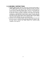
7. Attach the arm structures. Torque 7/8” bolster bolts to 250 lbf-ft.
8. Raise lift fully and wipe pistons down with a light coat of silicone lubricant
or WD-40.
9. Lower the lift and record oil level in the pumping unit.
10. Pressure check bleed-plugs by inspecting them through the hole in the
center of the lifting structures.
11. Check the hydraulic tee and the fitting on the pump for any leaks, tighten
if necessary.
CAUTION!
DO NOT FULLY RAISE LIFT WITHOUT SUPERSTRUCTURES
ATTACHED. THE PISTONS WILL COME OUT OF CASINGS AND
MAY BE DIFFICULT TO LOWER WITHOUT THE WEIGHT OF THE
SUPERSTRUCTURE ON THEM.
WHEN BLEEDING CYLINDERS, DO NOT ALLOW INNER
CYLINDERS TO ROTATE. THIS MAY CAUSE HOSE KINK.
KEEP ALL LIQUIDS AWAY FROM LIFT (water, cleaners, acids,
etc). ANY LIQUID WHICH GETS INSIDE THE LIFTING UNIT WILL
CAUSE INTERNAL DAMAGE AND WILL NOT BE COVERED
UNDER WHEELTRONIC’S WARRANTY.
17
Summary of Contents for 40HP210ES
Page 9: ...Figure 1 Bay Layout Option A 8 ...
Page 10: ...Figure 2 Bay Layout Option B 9 ...
Page 12: ...Figure 4 Elevation 11 ...
Page 14: ...Figure 5 Cable Routing 13 ...
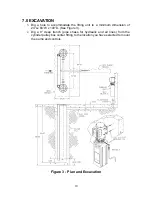
Page 15: ...Figure 6 Hydraulic and Air Connections 14 ...
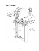
Page 25: ...16 0 LIFT ASSEMBLY 24 ...
Page 27: ...3 1026 1 Pump Stand Bolt Down Standard Not shown in figure 26 ...
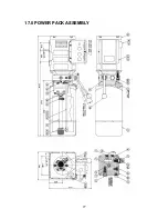
Page 28: ...17 0 POWER PACK ASSEMBLY 27 ...

