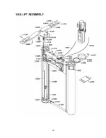
16.1 LIFT PARTS LIST
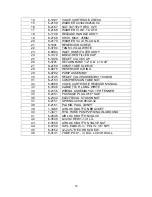
Part No.
QTY. Description
2-2525 4
Swing
Arm
1-3306 4
Sleeve
1-3307
4
Adapter Wing Pin
1-3309
4
High Flip Up Adapter Wing
1-3310
4
Low Flip Up Adapter Wing
3-1040
4
Flip Pad Assembly
6-0752 8
Circlip
½”
6-3487
4
Roll Pin 3/8” x 1”
1-3308 4
Arm
Bolt
2-2539 2
Equalizing
Cable
6-3530
2
7/16-14 Socket Head Cap Screw
6-3494
2
Hex. Nut 7/16”
6-3532
8
7/8” x 3” Hex HD Bolt G8
8-2546508
2
HCS 1/2-13” x 2” GR8 PLTD
2-2538
2
Locking Leg Weldment
2-2546 2
Trigger
Weldment
2-2547 2
Housing
Weldment
1-3361 2
Pulley
Assembly
30990
2
Hydraulic Cylinder – HP210ES
1-3330
8
Piston Block Holder
2-2541
1
Bottom Spacer Pipe Weldment
6-3493 12
Hex.
Bolt
7/16-14” x 1-1/4”L
6-3494
12
Hex. Nut 7/16”
1-3473
2
Hyd. Hose Cylinder 2P Inground
3-1000 2
Piston
Weldment
3-0997
1
Pulley Box Weldment
6-3523
1
Air Lock Cylinder
6-0709
1
Swl. Elbow, 14” Poly x 1/8” NPT
6-0126
4
Hex. Bolt, ¼” UNC x 1/2”, G5
6-3806
1
Bulkhead “T” 3/8” JIC Fitting
2-2544 1
Top
Cover
2-2540
1
Top Spacer Pipe Weldment
1-3471
1
Hyd. Hose Pump 2P/Sing Inground
6-3602
1
Lock Nut 1-1/2”
6-3603 1
“O”
Ring
6-3604
1
PVC Male Adapter 1-1/2”
8-0141
1
Tube, Poly., ¼” Dia. x 0.038” Wall
1-3333
1
Retainer Ring – Left 2P Inground
1-3332
2
8 3/8” ID Wiper
1-3518
1
Retainer Ring – Right 2P Inground
1-3312
8
Casing Bearing Block
2-2549
1
Wheelstop Spotting Plate
25
Summary of Contents for 40HP210ES
Page 9: ...Figure 1 Bay Layout Option A 8 ...
Page 10: ...Figure 2 Bay Layout Option B 9 ...
Page 12: ...Figure 4 Elevation 11 ...
Page 14: ...Figure 5 Cable Routing 13 ...
Page 15: ...Figure 6 Hydraulic and Air Connections 14 ...
Page 25: ...16 0 LIFT ASSEMBLY 24 ...
Page 27: ...3 1026 1 Pump Stand Bolt Down Standard Not shown in figure 26 ...
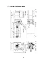
Page 28: ...17 0 POWER PACK ASSEMBLY 27 ...


