EN-11
2.0-1
SRA
2.0 INSTAllATION
2.0.1 MODElS WITH SRA ATTACHED
(OPTIONAL PART)
Once placed in the desired location the tire changer
must be bolted to the floor using anchors supplyed with
the machines with Safety Restraint Arm SRA. Concrete
must be steel mesh reinforced.
Tire Changer must be anchored to concrete floor
if equipped with a “Safety Restraint Arm”
(SRA)
.
2.0.2 INSTAllATION INSTRUCTION
The Tire Changer is delivered mounted to a wooden
skid. Remove tire changer from its mounts carefully,
taking care to avoid any back strain.
Install the machine in a covered and dry place. Place
the Tire Changer where proper operation will be
unobstructed to all sides. Operation temperature is
+41/+122 °F (+5/50 °C). The EHP Tire Changer can
work below 32 °F, but some minor modifications are
required: contact your
JBC
distributor for detailed
information.
Concrete must be a minimum of four inches commercial
grade, 3500-4000 PSI, with a cure time of at least 28
days. Steel mesh reinforced.
Follow these instructions carefully to insure proper and
safe operation.
A.
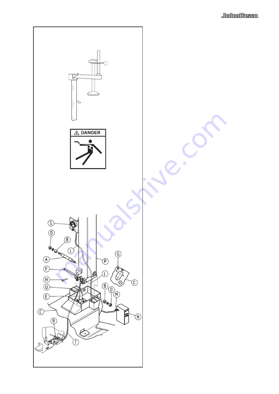
Remove the lube pail by unscrewing the relevant screw.
Remove the carter “
U
” (Fig.12) by unscrewing the
screws “
Z
” (Fig.2.0-1)
b.
Lift the column ‘
P
’ Fig.2.0-1 with an appropriate lifting
tool (crane, fork lift) and a belt of sufficient capacity
(2000N). For this operation it is required to be helped
by a second person. BE CAREFUL NOT TO DAMAGE
THE AIR HOSES. Introduce the air hoses ‘
l
’ through
the hole ‘
I
’ of the cabinet ‘
C
’.
Connect the air hose ‘
T
’ with the quick connector ‘
G
’.
C.
Mount the column ‘
P
’ as shown in Fig.2.0-1 and
connect it to the cabinet through shaft ‘
A
’, nut ‘
D
’ and
the conical bushings ‘
b
’.
IMPORTANT!
THE NUTS ‘D’ MUST BE TIGHTENED ENOUGH
TO ElIMINATE ANY SIDEWISE ClEARANCE
bETWEEN THE COlUMN AND THE CAbINET.


