background image

2

T 3300-24

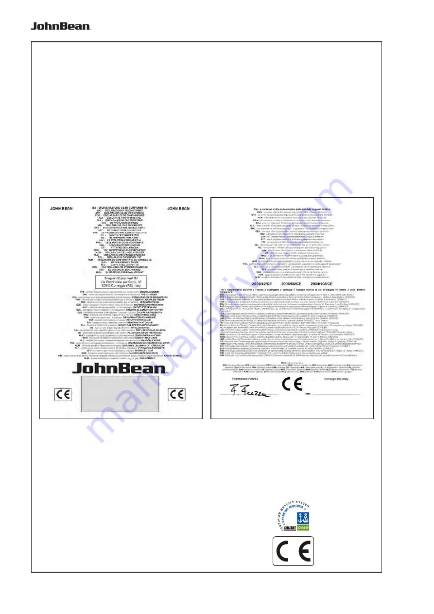
EC DECLARATION (

Original document contained in Spare Parts Booklet)

DECLARATION CE (

Le document original figurant dans le Liste des pièces détachées)

CE KONFORMITÄTSERKLÄRUNG (

Originaldokument in der Ersatzteilliste enthaltenen)

DICHIARAZIONE CE (

Originale contenuta nel Libretto Ricambi)

DECLARACIÓN CE (

El original se encuentra en tabla de repuestos)

DECLARAÇÃO CE (

O original está contida em Lista de peças)

- FACSIMILE -

All Information in this manual has been supplied by the producer of the equipment:

Toutes les informations figurant dans le présent manuel ont été fournies par le fabricant de l’équipement :

Alle in diesem Handbuch enthaltenen Informationen wurden durch den Hersteller der Maschinen geliefert:

Tutte le informazioni contenute nel presente manuale sono fornite dal produttore dell’apparecchiatura:

Todas las informaciones contenidas en este manual han sido facilitadas por el productor del equipo:

Todas as informações contidas neste manual foram fornecidas pelo produtor da máquina:

Snap-on


Equipment


 Srl a unico socio

Via Provinciale per Carpi, 33
42015 CORREGGIO (RE) ITALY
Tel. +39-(0)522-733480
Fax +39-(0)522-733479
E-mail:     corrcs@snapon.com
Internet: http://

www.snapon-equipment.eu

FFFFFAC

AC

AC

AC

AC

SIMILE

SIMILE

SIMILE

SIMILE

SIMILE

T3300-24 2 Speed

Summary of Contents for T 3300-24

Page 1: ...6000 T 6000 Operator s Manual T 6000 T 6000 Operator s Manual T 6000 T 6000 Operator s Manual T 6000 T 6000 Operator s Manual T 6000 T 6000 Operator s Manual T 6000 Electro Pneumatic Tire Changer Manuel del Operario Manuale d Uso ZEEWH545A05 Rev E Marzo 2014 Operator s Manual T 3300 24 2S BS ...

Page 2: ...rant dans le présent manuel ont été fournies par le fabricant de l équipement Alle in diesem Handbuch enthaltenen Informationen wurden durch den Hersteller der Maschinen geliefert Tutte le informazioni contenute nel presente manuale sono fornite dal produttore dell apparecchiatura Todas las informaciones contenidas en este manual han sido facilitadas por el productor del equipo Todas as informaçõe...

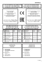
Page 3: ...EC DECLARATION EC DECLARATION CE CE KONFORMITÄTSERKLÄRUNG Wiring Diagram WD Schéma électrique Schaltplan Pneumatic Diagram PD Schéma pneumatique Pneumatikschema DICHIARAZIONE CE EC DECLARACIÓN CE DECLARAÇÃO CE Schema Elettrico WD Esquema Eléctrico Esquema Eléctrico Schema Pneumatico PD Esquema Neumático Esquema Pneumático Contenuto in SP Integradas en SP Conteúdos em SP Contained in SP Contenu dan...

Page 4: ...mounting a tyre 30 9 Mounting a tyre 32 10 Inflating a tyre 34 11 Maintenance 40 12 Technical data 42 13 Unit 44 1 General 1 1 Tips for the reader Special symbols are used in this manual to facilitate reading and understanding of pictures and written instructions Bulletsindicatewhereanaction operationisrequired 1 2 Scope T 3300 24 T 3300 24 BS The T 3300 24 BS tyre changer is designed to demount a...

Page 5: ...sorios no aplicables al modelo consultado Utilizar los códigos de la lista para realizar los pedidos de compra Las normas de seguridad están escritas sobre fondo gris Indice Pag 1 Generalità 5 2 Installazione della macchina 13 3 Collegamento della macchina 17 4 Stallonatura 19 5 Bloccaggio delle ruote 23 6 Impostazioni della testina di montaggio 27 7 Principi di smontaggio e montaggio 29 8 Smontag...

Page 6: ...trical system such as fitting of a plug or changing of connections if necessary must be carried out by a qualified electrician in line with relevant national standards and the regulations of the local power station In general it should be noted that working with technical equipment may involve unforeseen residual risks Therefore various self explanatory warning labels yellow black triangle are fit...

Page 7: ...os facilitados por el fabricante de la máquina o por el fabricantedelproductoempleado Para conocer las demás normas de seguridad a seguir véanseloscapítuloscorrespondientes 1 3 Norme generali di sicurezza Glismontagommedevonoessereutilizzatiesclusivamente dapersonaleautorizzatoeadeguatamenteaddestrato Qualsiasi modifica o variazione dell apparecchiatura non preventivamente autorizzata dal costrutt...

Page 8: ...st is only tilted back to its working position on the rim flange A pneumatic tyre bead breaker for demounting tyres fitting tightly to the rim is incorporated in the machine and is part of the standard equipment A manual tyre inflator is also part of the equipment Upon special request the machine can be provided with a jet tyre inflating system For its operation and use see chapter Inflating the t...

Page 9: ...speed BS también está equipado con sistema BS de hinchado de los neumáticos ya descrito anteriormente 1 4 Descrizione del funzionamento Il bloccaggio del cerchio l inclinazione del palo montante e l arresto della torretta nella relativa posizione di lavoro hanno luogo in modo pneumatico Il piatto autocentrante a quattro griffe regolabili è azionato da un motore elettrico tramite una cinghia trapez...

Page 10: ...speeds Depress pedal to first stage 7 rpm tyres difficult to handle Fully depress pedal 14 rpm tyres easy to handle Lift pedal backward rotation of chuck at 7 rpm only 13 Machine dimensions 14 Bead breaker 15 At the rear side of the machine the connector for the manual tyre inflator only for basic versions not BS 16 Bead holding device optional 17 Pressure gauge only for BS versions all with tool ...

Page 11: ...ncorpora un selector 1 Fig 1a ON OFF 0 1 con el que el operador puede activar o desactivar la alimentación eléctrica de la máquina ATENCIÓN SE RECOMIENDAAPAGAR LA UNIDAD AL TERMINAR LA JORNADA DE TRABAJO 1 5 Elementi della macchina Fig 1 Vista globale della macchina 1 Testina di montaggio a regolazione verticale 2 Leva a pulsanti nell ingrandimento per bloccare la testinadi montaggio nella sua pos...

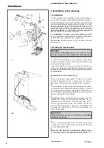
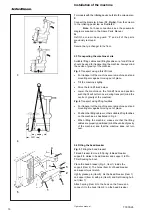
Page 12: ... machine some important parts may need to be reassembled Although these are simple operations we recommend that you follow the instructions provided below Mounting the vertical column Fig 2 A Remove the column base guard 1 and the two lateral holders if present from the machine Cut and remove the straps holding the shaped washers 2 in position B Lift the column 0 with an appropriate lifting tool c...

Page 13: ...D Mover la columna hacia atrás Tirar de la barra 8 del pistón y conectarla con la columna usando el perno 9 Bloquear el perno con el pasador 10 E Desmontar el lateral izquierdo de la máquina y conectar el tubo de aire 3 movimiento de la herramienta al racor 2 Installazione della macchina 2 1 Installazione Lo smontagomme può essere installato su qualsiasi fondo in cemento o pavimentazione di pari d...

Page 14: ...e on the fork lift truck and position such that it will not turn over during transport mind the centre of gravity of the machine Fig 4 Transport using lifting facilities For transport of the machine secure machine post and mounting arm against moving out of place Position the lifting cables or other suitable lifting facilities on the machine as illustrated in Fig 4 When lifting the machine make su...

Page 15: ... muelle 3 al gancho que se encuentra sobre el bastidor y al gancho 2 del destalonador E Rimuovere la fiancata sinistra della macchina e collegare il tubo dell aria 3 movimento utensile al raccordo 11 della pedaliera I modelli con dispositivo di gonfiaggio integrato nel palo necessitano inoltre di F Collegare il tubo diametro 8 12 Fig 2a proveniente dal palo al rubinetto del pedale di gonfiaggio co...

Page 16: ...al system that the machine is connected to is fitted with 10 A delayed fuses in case of machine with INVERTER 20 A 25 A for Japan or alternatively an equivalent automatic magneto thermic switch Check that there is an efficient earthing system Once the connection is complete press the self centring rotation pedal downwards 1 Fig 6 and check that it rotates clockwise Check that the power supply syst...

Page 17: ...8 a 10 bar utilizando un tubo neumático con un diámetro interno de 8 mm 5 16 Para más información consultar el esquema neumático que se ilustra en la lista de piezas de recambio 2 5 Collegamento elettrico ATTENZIONE Qualsiasi intervento sull impianto elettrico ed il collegamento di una spina se necessario deve essere realizzato esclusivamente da un elettricista qualificato nell osservanza della no...

Page 18: ...ment of the bead breaker blade and travel of the blade during the bead breaking operation Adjusting the blade angle and oscillation Both the penetration angle of the blade on the tire beak and the free oscillating movement limit operated during bead breaking can be adjusted using the screw knob and the lock nut 1 2 Fig 7 Adjusting the PENETRATION ANGLE Turn the lateral adjustment knob 1 to determi...

Page 19: ...ta Después de haber ajustado el ángulo se podrá vincular establemente la paleta aflojando completamente la contratuerca 3 Stallonatura Gli smontagomme standard sono normalmente dotati di stallonatore per pneumatici Si noti che i cerchi per ruote Tubeless o i cerchi asimmetrici debbono essere trattati in modo particolare 3 1 Regolazione della paletta stallonatrice Versione 2 speed 24 e 2 speed 24 G...

Page 20: ...t with the tyre If necessary move the jaws inside Lean the deflated wheel on the side against the special rubber pads provided at the machine housing Position the bead breaker blade Fig 9 Item 1 on the outside of the tyre approximately 1 cm away from the edge of the rim using the adjustable handle for accurate positioning Depress pedal Fig 9 Item 2 The blade moves in between tyre and rim Release t...

Page 21: ...ocando lubrificante en el punto en el que la paleta destalonador acaba de penetrar en la base de la llanta No usar nunca agentes pseudo lubrificantes 3 1 1 Regolazione in larghezza Fig 8a Per incrementare anche lo spazio utile per il pnuematico sollevare il perno 3 sfilare la paletta 1 dopodichè inserire nella propria sede il perno 3 Pos A La paletta ruota ma non si sfila Pos B la paletta non ruot...

Page 22: ...10a then take your foot off the pedal The wheel is clamped Fig 11 Depress the pedal past the lower end of stroke position then release it The wheel is unclamped Rims with an asymmetrically arranged drop base should be positioned so that the narrow rim shoul der faces upwards see rim in Fig 11 The clamping jaws can be preset for wheels that are difficult to clamp sidewall of tyre is very stiff 4 2 ...

Page 23: ...ahaciaabajomanualmente sobre el dispositivo de centrado automático Bajar el pedal más allá de la posición de paro y soltar La rueda quedará bloqueada 4 Bloccaggio delle ruote Prima di bloccare una ruota sbloccare la torretta Fig 10 Pos 1 portare la torretta nella posizione più alta spingere indietro il braccio di montaggio fino a finecorsa e bloccare nuovamente Azionare il pedale Fig 10 Pos 3 per ...

Page 24: ...own on the turntable manually Depress pedal past the end of stroke position and release it The wheel is clamped 4 3 Fitting special clamping jaws Special clamping jaws are simply positioned on the clamping jaws already present and snapped into place To install any accessory on request follow the instructions enclosed with it 4 4 Inner clamping of rims with a diameter of be tween 12 and 22 for Basi...

Page 25: ...el exterior Para bloquear las llantas de aleación en una impecable como opcional se encuentran disponibles capuchones de plástico especiales para quijadas Versione 2 Speed 24 Attenzione Verificare che le quattro griffe di bloccaggio siano montate nella stessa posizione Fig 13 Pos 1 o 2 Altrimenti ilcerchiopuòallentarsiecausarelesioni Molto Importante verificare il corretto inserimento del perno Pr...

Page 26: ...4 Item 5 The machine post is tilted into working position Release the locking mechanism of the mounting head Move the mounting head by hand to the rim flange and position onto the rim Mounting nose and bead guide roller might contact the rim Operate the push button Fig 14 Item 2 to set and lock the mounting head automatically in working position with respect to height and lateral clearance Fig 15 ...

Page 27: ... la llanta Después de haber regulado de nuevo el cabezal volver a apretar el tornillo de fijación 1 5 Impostazione testina di montaggio Prima di smontare o montare un pneumatico occorre accertarsi che il braccio di montaggio sia retratto completamente e la testina di montaggio si trovi in posizione sollevata Quando si opera su varie ruote delle stesse dimensioni la testina di montaggio può rimaner...

Page 28: ...damaged surface of rim flanges lateral and radial run out of rim corrosion wear in general 4 With some tire types pay attention to the outer sidewall rib or to direction of rotation as indicated on the tire 5 When inflating the tire increase pressure gradually and possibly by constantly observing the bead A seating pressure of 3 3 bar should not be exceeded Make sure the mounting guide rib of the ...

Page 29: ...eumáticos TD no pueden equiparse con cámara de aire 8 En cualquier caso seguir siempre las instrucciones específicas para el montaje y el desmontaje facilitadas por los productores de los neumáticos 6 Montaggio e Smontaggio pneumatici Principi fondamentali 1 Usare le speciali parti in plastica per il bloccaggio la te stina di montaggio in plastica e le speciali leve per pneumatici ricoperti o simi...

Page 30: ...8 A Depress pedal 1 Fig 17 to start turntable rotation Leave the tyre lever on the mounting demounting tool arm and press against the latter arrow Fig 16 until part of the tyre bead has gone over the rim flange Remove the tyre lever and rotate the turntable further Continuing the demounting make sure the part of the tyre bead opposite the mounting demounting tool is in the drop base and avoid exce...

Page 31: ...rectamente sobre la herramienta de pico flecha Fig 18 B Tras haber desmontado el neumático 2 Fig 17 presione el pedal para inclinar el palo montante atrás 7 Smontaggio di un pneumatico Durantelosmontaggiodiunpneumaticorispettaresempre lelineeguidadellaWdK Losmontaggiodiunpneumatico risulta notevolmente facilitato se viene preceduto dall applicazionediunlubrificantecommercialesultallone e sul bordo...

Page 32: ...ead guide roller arrow Fig 20 A Start mounting by operation of pedal 1 Fig 17 During the mounting process observe correct bead run otherwise stop and correct by hand then proceed until the tire bead has gone completely over the rim flange In case of tubed tires put on the tube after mounting of the lower tire bead To ensure that the tube is not dam aged once fitted pay attention to tube position a...

Page 33: ...ue el talón del neumático quede montado completamente Para hinchar el neumático soltar el bloqueo de la rueda 8 Montaggio di un pneumatico Attenersi sempre alle norme vigenti in materia di montaggio dei pneumatici nella nazione in cui si opera Montare il pneumatico può essere più o meno facile a seconda se prima del montaggio si è applicato un comune lubrificante per pneumatici sul tallone e sul c...

Page 34: ...ed 3 5 bar 9 1 General information about tire inflating devices For use in Germany tire inflating devices Fig 22 26 are subject to German law with respect to calibration Official Journal Measuring and calibration system law of 11 July 1969 paragraph one No 2 section 3 Pressure gauge calibration lasts for two years after the end of the calendar year in which the equipment was last calibrated For ca...

Page 35: ...tivos de seguridad por ej una cabina de seguridad de los dispositivos de retención etc Se l autocentrante si ferma durante il montaggio per effetto di un eccessivo attrito sul tallone fermare la procedura ruotare leggermente indietro l autocentrante premere il tallone già montato con forza verso il basso nel cerchio eventualmente utilizzare un premitallone e continuare con il montaggio Se i pneuma...

Page 36: ...TO AVOID EXCESSIVE PRESSURE BEFORE BEADING CHECK THE CONDITION OF TIRE AND RIM CHECK FOR CORRECT SEALING BETWEEN THE VALVE AND THE FITTING AT THE END OF THE AIR HOSE AN AIR LEAK CAN GIVE INCORRECT PRESSURE READINGS AND CREATE SAFETY HAZARDS CHECK THAT THE READING ON THE PRESSURE GAUGE IS ZERO WHEN IT IS NOT IN USE THE COMPLETE SEATING THE BEAD ON THE RIM IS A VERY DANGEROUS STAGE OF THE TIRE MOUNT...

Page 37: ...ÁMETRO DE 1 2 INFERIOR A LA LLANTA EN LA CUAL SE ENSAMBLAN NO SE GARANTIZARÁ LA ADHERENCIA ADECUADADE LOS TALONES EN SUS SEDES LO CUAL SUPONE UN PELIGRO PARA LA GUÍA 9 2 Intallonatura dei pneumatici Per Intallonatura si intende l iniziale aderenza dei talloni del pneumatico al cerchio tale da consentire il proseguo dell operazione di gonfiaggio e sucessivo assestamento degli stessi nelle proprie s...

Page 38: ... vertical position and bounce it while introducing air with the pedal control or with the nozzle Fig 24 Beading with the nozzle device The machine can be provided with a GT device necessary for bead seating of tubeless tires Connect the compressed air hose to the valve 1 Fig 23 Position the GT device beading nozzle between tire and rim pointing the air jet inside the tire 2 Fig 23 Press the inflat...

Page 39: ...O DURANTE EL ACCIONAMIENTO DEL DISPOSITIVO DE ENTALONADO ES OBLIGATORIO EL USO DE AURICULARES Y GAFAS DE PROTECCIÓN PARA EVITAR LA CONTAMINACIÓN POR POLVOS E IMPUREZAS LEVANTADAS POR EL CHORRO DE AIRE Intallonatura di Pneumatici Tubeless Operare l Intallonatura con la ruota bloccata sullo smontagomme Accertarsi che entrambi i talloni e l interno del cerchio siano accuratamente lubrificati Avvitare...

Page 40: ... inflation hose to the valve stem C Lift the tire with both hands so that upper bead is sealed to the rim edge Fig 26a D Press the inflation pedal down swiftly The top bead is already sealed by the lifting motion The air from the bead seater jets will rebound into the bottom sidewall driving it into place and creating a seal E Complete inflation as described at the beginning of this section WHEN O...

Page 41: ... DISPOSITIVO DE HINCHADO ES OBLIGATORIO EL USO DE AURICULARES CONTRARUIDOSYANTIPARRAS DE PROTECCION PARA EVITAR LA CONTAMINACION CON POLVOS E IMPUREZAS LEVANTADAS POR EL CHORRO DEAIRE Qualora la macchina presentasse il sistema di intallonatura per pneumatici Tubeless integrato negli scorrevoli del piatto autocentrante seguire la proce dura di seguito indicata IntallonaturacondispositivoTubelessall...

Page 42: ...rly drain the condensation from the filter collector 3 Fig 27 To do so turn the locking ring 4 Fig 27 anti clockwise Once a month disconnect the machine from the compressed air network 2 Fig 27 and clean the filter condensation collector 3 Fig 27 At least once a year clean the worst of the dirt from the bearings guides and the like and keep them running smoothly At least once a year lubricate with...

Page 43: ...ment eu Hotline International 49 8634 622 8996 Hotline German 49 8634 622 8994 Reception 49 8634 622 0 Snap on Equipment Germany Konrad Zuse Straße 1 D 84579 Unterneukirchen 10 Manutenzione Prima di eseguire interventi di manutenzione scollegare la macchina dalle reti di alimentazione e bloccarla contro la riaccensione accidentale In generale per gli interventi di manutenzione rispettare le norme ...

Page 44: ...h 50 60Hz 20A Turntable rotation 1st speed 7 rpm 2nd speed 14 rpm Torque at 7 rpm 1200 Nm Installed power at 7 rpm 0 80 kW Torque at 14 rpm 800 Nm Installed power at 14 rpm 1 1 kW Basic version Version 2 Speed with special jaws for trolley and mini wheels 7 13 with special jaws for light truck wheels 17 5 Max wheel diameter 990 mm Compressed air supply 8 15 bar Bead breaker force at 10 bar pressur...

Page 45: ...ites a utilizar con aceitera TAMOIL WHITE MINERAL OIL 15 SHELL ONDINA OIL 15 BP ENERGOL WT3 TOTAL LOBELIA SB 15 ESSO MARCOL 82 11 Dati tecnici Versione base Gamma di bloccaggio esterno 10 20 Gamma di bloccaggio interno 12 22 con griffe di serraggio per motociclo 15 23 Gamma di stallonatura 1 12 40 340 mm Larghezza cerchi 3 12 Motore 1 velocità Collegamento elettrico Std 400 Vac 3Ph 50Hz 2 3A 230 V...

Page 46: ...pment At the time of disposal at the end of the lifetime of this equipment you must 1 NOT dispose of the equipment as municipal waste and separate collection is mandatory 2 Ask the retailer about collection points authorised for regular disposal 3 Stick to the standards for correct waste management to prevent potential effects on the environment and human health This symbol indicates that separate...

Page 47: ...e las personas Este símbolo indica la obligación de llevar a cabo una recogida diferenciada de los aparatos eléctricos y electrónicos al momento del desguace 12 Eliminazione e smaltimento Al momento dello smaltimento dell unità contattare il rivenditore per una offerta o per conoscere le disposizioni per lo smaltimento previste per l unità 12 1 Istruzioni di smaltimento Per apparecchiature elettri...

Page 48: ...Incorporated Emesso in Marzo 2014 copyright 2014 Snap on Technologies P N ZEEWH545A05 Rev E EUROPE MIDDLE EAST AFRICA JAPAN Snap on Equipment s r l Via Prov Carpi 33 42015 Correggio RE Italy Phone 39 0522 733 411 Fax 39 0522 733 479 www snapon equipment eu France Snap on Equipment France ZAdu Vert Galant 15 rue de la Guivernone BP97175 ST Ouen L Aumone 95056 Cergy Pontoise Cedex Phone 33 0 1 3448 ...

Reviews: