Operator’s manual
Notice d’utilisation
Betriebsanleitung
T 4500-24
27
T4500-24_ GB-FR-DE - Release A Februar 2010
JOHN BEAN EQUIPMENT GROUP reserves the right of modification without notice
T4500-24_GB-FR-DE – Rev A Février 2010
Document non contractuel
T4500-24_GB-FR-DE - Release A February 2010
JOHN BEAN EQUIPMENT GROUP behält sich das Recht zu Änderungen ohne Vorankündigung vor
LIBERAL LUBRICATION OF
THE TIRE AND RIM IS NECES-
SARY TO MOUNT TIRE CEN-
TERING CORRECTLY AND
GET A PROPER ON THE RIM.
BE SURE YOU ARE USING
APPROVED LUBRICANT
ONLY.
B.
Lock the rim on the turntable and rotate
it to have the valve in 5 o'clock position.
Place the tire to be mounted on the rim.
Tilt the column forward so that the
mount/demount tool is in the working po-
sition.
ENSURE THAT THE
MOUNT/DEMOUNT TOOL IS
NOT PRESET TO A WRONG
POSITION SOTHAT IT WILL
HIT THE RIM EDGE AND
CREATE AN HAZARD, BE-
FORE TILTING THE COLUMN
FORWARD.
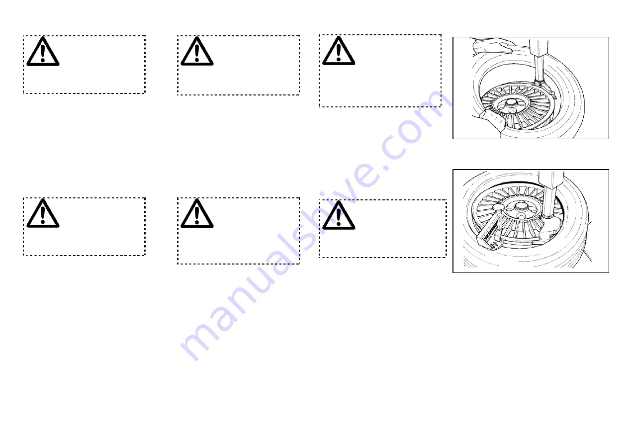
Engage the lower bead OVER the moun-
ting wing and UNDER the mounting finger
of the mounting tool. Turn the wheel
clockwise and push the tire down into the
drop center, opposite to the
mount/demount head (Fig. 28).
C.
Mount the upper bead following the di-
rections in section B (Fig. 29). With low
profile tyres the bead depressor tool
“MX” (optional EAA0247G70A) can help
to facilitate mounting of the top bead.
UNE LUBRIFICATION ABON-
DANTE EST NECÉSSAIRE
POUR MONTER LE PNEU
CORRECTEMENT ET OBTENIR
UN BON CENTRAGE SUR LA
JANTE. UTILISER SEULEMENT
DES LUBRIFIANTS SPÉCIFI-
QUES POUR PNEUS.
B.
Bloquer la jante sur l'autocentreur et
la tourner pour avoir la vanne sur 5h.
Mettre le pneu sur la jante. Mouvoir la
potence en avant et mettre l'outil en
position de travail.
S’ASSURER SI L’OUTIL DE
MONTAGE/DEMONTAGE
N’EST PAS BLOQUE DANS
UNE POSITION INCORRECTE,
TELLE QUE L’OUTIL PEUT
HEURTER LE BORD DE LA
JANTE, AVANT DE BASCU-
LER LA POTENCE EN POSI-
TION DE TRAVAIL.
Engager le talon inférieur AU-DESSUS
de l'ailette de montage et EN-
DESSOUS de la languette de l'outil.
Faire tourner l'autocentreur dans le
sens des aiguilles d'une montre et
pousser le talon dans le creux en po-
sition opposée à l'outil (Fig.28)
C.
Monter le talon supérieur de la même
façon. Pour les pneus taille baisse,
utiliser l'étau de montage 'MX' (en
option EAA0247G70A) (Fig. 29).
EINE AUSGIEBIGE SCHMIE-
RUNG IST ERFORDERLICH,UM
EINE EINWANDFREIE REI-
FENMONTAGE ZU ERREI-
CHEN UND EINE KORREKTE
REIFENZENTRIERUNG AUF
DER FELGE SICHERZUSTELLEN.
DAZU NUR SPEZIAL-
SCHMIERMITTEL FÜR REIFEN
VERWENDEN.
B.
Die Felge auf der Spannvorrichtung
spannen und soweit drehen, bis sich
das Ventil in 5-Uhr-Position befindet.
Den Reifen auf die Felge legen. Die
Maschinensäule nach vorn bewe-
gen, so daß das Demontagewerk-
zeug in Arbeitsstellung gebracht wird.
VOR DEM ZURÜCKKIPPEN DER
SÄULE IN ARBEITSPOSITION
SICHERSTELLEN, DASS DAS
MONTAGE/DEMONTAGEWER-
KZEUG NICHT IN FALSCHER
POSITION ARRETIERT IST UND
SOMIT GEGEN DAS FELGEN-
HORN SCHLÄGT.
Den unteren Wulst AUF den Montage-
flügel heben und UNTER den Montage-
finger schieben. Den Spannteller im
Uhrzeigersinn in Bewegung setzen, und
dabei den Wulst auf der dem Monta-
ge-werkzeug gegenüberliegenden Sei-
te ins Tiefbett drücken (Abb.28).
C.
Den Vorgang mit dem oberen Wulst
wiederholen. Bei Reifen mit niedrigem
Querschnitt ist die Verwendung der
Montageklemme MX (Sonder-zubehör
EAA0247G70A) hilfreich (Abb. 29).
338
Fig. 28
339
Fig.29


