Page 16
5.0 TIRE MATCHING PROGRAM - F90
Tire matching assists the user in determining the best
possible mating of the tire and rim. The mating of tire
and wheel normally allows the least amount of additional
weight required for balancing and total runout.
The matching program is helpful when:
•
Excessive radial runout is noticed.
•
The balancer calls for weights in excess of 2 oz. on
either plane in the
Dynamic
mode.
The
VPI System III
computer wheel balancer features a
matching program capable of two levels of resolution:
Dynamic
, to rotate
and
reverse the tire on the rim for
optimum rim and tire matching.
Static
, when the tire has an ornate sidewall or direc-
tional tread and cannot be reversed on the rim.
INSTRUCTIONS:
1. Press the "
F
" button followed by rotating the shaft
until the display. reads "
F
" “
90
”, release the "F"
button.
When activated the machine displays "
--- ACH---
" for
one second followed by "
PUT VAL tOP
". This instructs
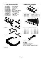
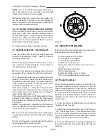
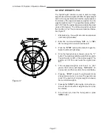
the operator to rotate the wheel so the inflation valve is
at 12 o'clock. See
Figure
26. Press "F" to store the
valve position, the display will then read "
ACH SPN 1
".
NOTE
: THE F BUTTON CAN BE PRESSED MORE
THAN ONCE, EVERY TIME THE F BUTTON IS
PRESSED, THE VALVE POSITION IS REMEMBERED
BY MACHINE AS A REFERENCE POINT.
2. Lower the wheel guard to spin the wheel, when the
shaft reaches the balancing speed, the display reads "
-
-- ACH ---
" accompanied with a short beep.
3. After spinning the shaft brake engages and the dis-
play reads "
tur tir---
" and "
CrS tOP---
" alternatively.
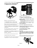
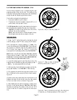
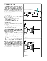
(1) The operator should turn the wheel and mark an X at
the 12 o'clock when the valve is at the 6 o'clock position.
Figure
27
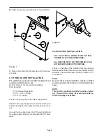
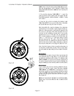
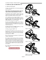
(2) Remove the wheel assembly from the balancer and
deflate and rotate the tire on the rim so the valve points
to the cross mark on tire as shown in
Figure
28
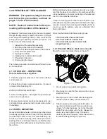
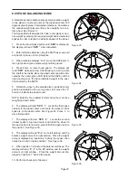
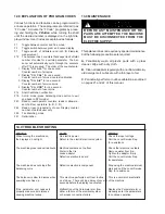
4. After inflating the tire and remounting on shaft, press
F Button. The machine displays "
PUT VAL tOP
" again.
Operator should turn the wheel so the valve is at 12
o'clock. Press the "F" button to program the valve posi-
tion.
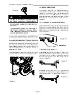
Figure 26 - Step 1, valve top, press "F"
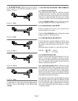
Figure 27 - Step 2, valve at bottom,
mark top of tire with X, press "F"
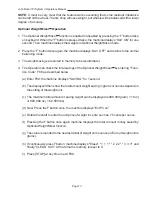
Figure 28 - Step 3, rotate tire on wheel so the valve and
X mark line up. Rotate assembly to TDC, press "F".
Summary of Contents for VPI SYSTEM II
Page 2: ......
Page 27: ...NOTES ...

