ROTOR PROCESSORS (ROTOR) |
15
Rotor Processors
(Rotor)
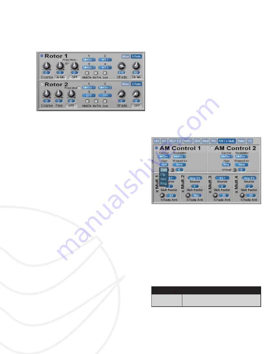
Figure 14: Rotor Processor Pair
The Rotor object is a module created by Michael Ruf,
former product manager at Creamware. His idea came
from the rotary engine model, which has 4 power cyl-
inders, and where each cylinder’s explosion sends the
rotor on to the next position.
In the Rotor circuit here, there are no explosions (well,
maybe sonically!), but the concept of continuously mov-
ing from one cylinder to the next is in force. Here’s how
it works:
There are four inputs to the Rotor. Each is presented
at the Rotor’s output in series, one after the other.
(You can think of it as a 4-step wave sequence, where
each step’s sound comes from one of the many sound
sources in Solaris.) The XFade ( Crossfade) control
‘smoothes’ the transition from one step to the next, and
does it uniformly for all four inputs. If the XFade amount
is zero (0), then the transition from one step to the next
will be abrupt; at full amount (127), each step is cross-
faded with the next, providing smooth but constant
changes in the output. When the Rotor runs at audio
rates, the transitions happen so quickly that we hear
the results as a unique waveshape itself – one can
change either the coarse and
fi
ne tunings of each input,
or the source material itself to create timbre changes.
You’ll also
fi
nd (at audio rates) the Xfade amount
makes the waveform less bright as you move from zero
to max amount, as the smoothing function takes off the
‘rough edges’ of the resultant as it is increased. Ad-
ditionally, a modulation path is provided for modulating
the Xfade amount.
There are two page buttons in the upper right section
for each Rotor – Mixer and X-Fade. Clicking on the
‘Mixer’ button switches out the display to show four
small mixer knobs. These allow you to precisely set
each level of the four inputs, in the case of an imbal-
ance of levels from the sound sources. Also, the mix
levels are bipolar, for inverting the phase of the incom-
ing signal.
Clicking back to ‘X-Fade’ displays the initial Crossfade
(Xfade) control for the Rotor, as well as a modulation
path for this parameter. The higher the crossfade num-
ber, the smoother the transition from one input to the
next will be.
One unusual way of generating new harmonic struc-
tures is to run the Rotor at audio rates, tracking the
keyboard. This is almost like a ‘granular’ approach in
that you will hear small bits of each input at a rapid
rate. As mentioned, increasing the crossfade in this
case gives the impression of a ‘less bright’ harmonic
content, as the crossfade smoothes out the ‘rough
edges’ of the resultant waveshape.
AM Synthesis
(AM/ xMult.)
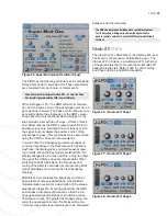
Figure 15: AM Synthesis Section
Amplitude Modulation (AM) is a process of varying the
amplitude of one sound (the carrier) by the amplitude of
another (the modulator). If the frequency of the modula-
tor is sub-audio, AM results in a tremolo effect. If the
modulator’s frequency is above around 10hz, the tim-
bre of the carrier is affected by the introduction of ad-
ditional partials to the output. When two sine waves are
used, AM results in two additional sidebands equally
spaced around the carrier’s fundamental frequency.
The frequency of the sidebands is the sum and differ-
ence of the carrier and modulator’s frequencies, and
the amplitude of the new partials is half the amplitude
of the carrier.
Algorithm
Description
Shift
Typical AM that produces two side-
bands around the carrier


