20
| SOUND MODIFIERS
can have a different combination of sound sources
sent to each of the
fi
lters at the same time. There is a
gain boost after the
fi
lter signal, and the signal output
path from each
fi
lter is then sent to the pan and level
section. (If the upper Filter section is disabled, the raw
Mixer output is sent to the pan and level sections.)
Each Filter Level can be controlled by a knob on the
surface, by any of the envelopes, or any of the other
modulation sources listed. Using these, you can create
separate articulated shapes for each
fi
lter’s output - al-
most a ‘multi timbre’ approach to the sound, enhanced
by the fact that each can also have its own envelope
and pan position.
With the Filter outputs as possible signal inputs, you
can create feedback loops within each
fi
lter section, or
have the function of series
fi
lter connections (the
fi
lter
output is taken before the pan module, so the series
fi
lter signal’s panning is determined by the last
fi
lter in
line). You also can get some useful and strange distor-
tion of the
fi
lters if desired, among many, many other
things!
Filter Page Views
The Filter Section has two main views, the main Filter
+ Filter Mixer pages for
fi
lters 1-4 and the
fi
lter Output
page. Clicking on F1, F2, F3 or F4 will display the
fi
lter
and
fi
lter mixer settings for that
fi
lter. Solaris’
fi
lter sec-
tion consists of:
Page
Description
F1
Filter 1 Mixer/Filter section
F2
Filter 2 Mixer/Filter section
F3
Filter 3 Mixer/Filter section
F4
Filter 4 Mixer/Filter section
Outputs
An overview of the key parameters of all 4
fi
lters and
fi
lter mixers in one view
Filter Pages
Table 4:
The control pages for
fi
lters 1-4 can be accessed by
clicking on the page buttons F1-F4, respectively. The 4
Mixer/Filter sections are identical, and each section is
composed of:
A
fi
lter which can be activated or bypassed
•
A four channel input mixer: This pre-
fi
lter mixer
•
gives access to up to four oscillators’ signals (which
means up to 4x4…16 separate oscillators for the all
fi
lter sections)
The Filters
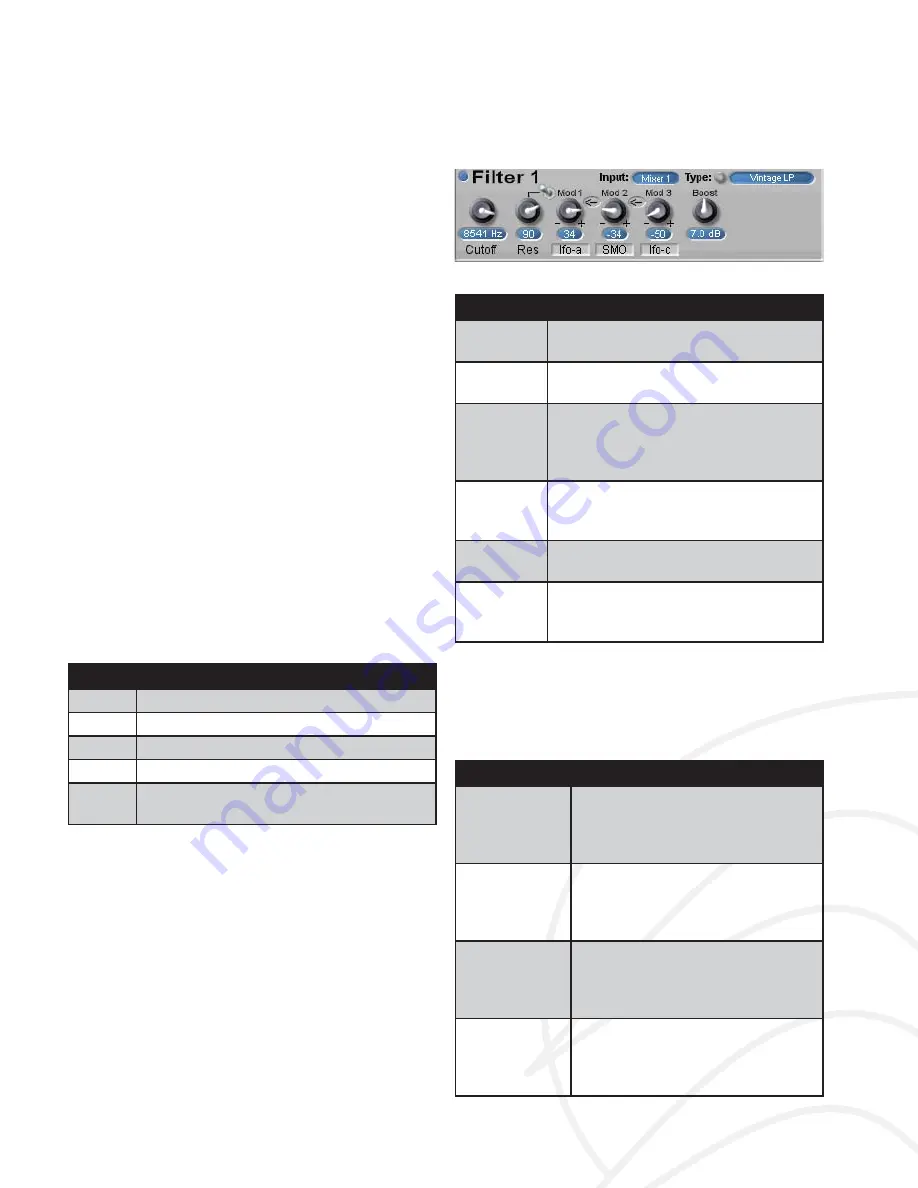
Figure 19:
Filter Panel
Control
Description
On/Off LED
(Blue LED in top left corner). Of
fl
oads
the
fi
lter from the DSP when Off
Cutoff
This is the frequency of the
fi
lter – from
12-20000 hertz
Res
Resonance control. Each
fi
lter type will
have a different resonance character-
istic, so you will need to adjust this as
you change the
fi
lter type
Mod1
Switch to
Res
This switches the modulation destina-
tion of the Mod1 path from the
fi
lter
cutoff to the
fi
lter’s resonance
Mod 1, Mod
2, Mod 3
These control the modulation path to
the
fi
lter cutoff
Boost
Up to 12 dB of gain can be applied
post-
fi
lter. High levels will give a distor-
tion that may or may not be desired
Filter Controls
Table 5:
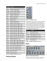
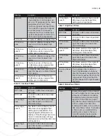
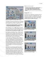
Solaris features a large number of
fi
lter types, from
emulations of classic analog
fi
lters to several speciality
fi
lters. The tables below list the available
fi
lters by
fi
lter
type:
Filter Type
Description
Vintage LP
When you increase resonance,
the typical
fi
lter circuit causes a
reduction in the input signal level. A
4-pole, 24 dB slope
fi
lter.
CEM Lowpass
Emulation of the Curtis ElectroMu-
sic chip used in the Pro One and
Prophet synths. A 4-pole, 24 dB
slope
fi
lter.
SSM Lowpass
Emulation of the Solid State Music
chip used in the Rev.1 and Rev.2
Prophet synths. A 4-pole, 24 dB
slope
fi
lter.
Mini Lowpass
Emulation of the
fi
lter used in the
Minimoog. A 4-pole, 24 dB slope
fi
lter with saturation. Input levels
easily distort.
Schwein - Fantasia


