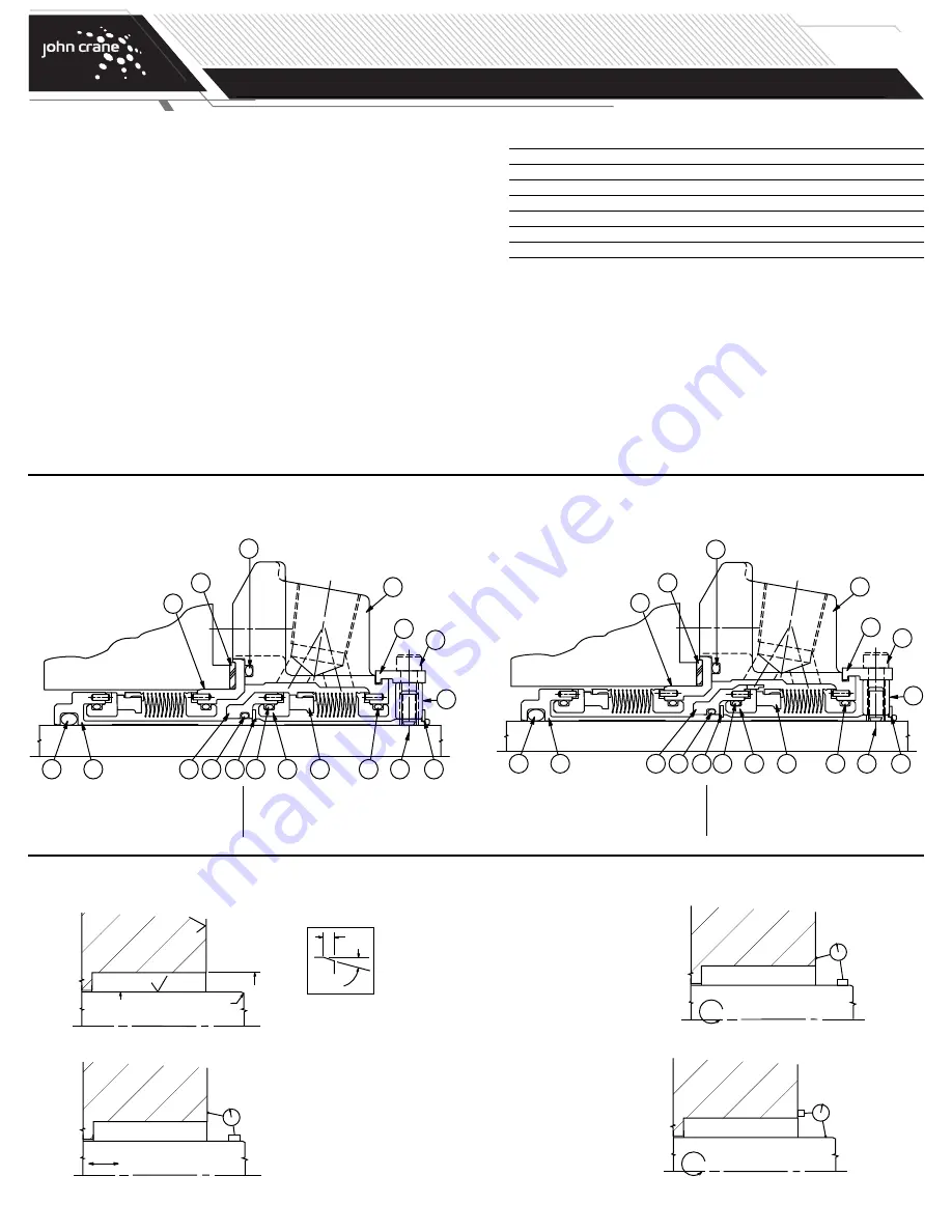
Typical Type 5625 Dual Metal Bellows Cartridge
Seal Arrangement
17
4
6
5
16
13
2
18
1
3
8
14
15
12
11
7
9
10
General Instructions
1.
Study the engineering layout drawing to confirm the proper seal
arrangement for the pump being used. Type 5625 and 5625P seals
are designed for versatility and can be assembled in various ways.
The following instructions describe the standard configurations.
2.
To assure satisfactory operation, handle seal with care. Take particular
caution to see that the lapped sealing faces are not scratched or
damaged.
Preparing the Equipment
1.
Check seal chamber dimensions and finishes.
2.
Measure axial end play (0.003" FIM max.).
3.
Determine squareness of seal chamber face to shaft:
Rotating Mating Ring
- 0.005" FIM max.
Rotating Seal Head
- 0.002" FIM max.
4.
Measure shaft runout (0.002" FIM max.).
63
BORE
SHAFT OR SLEEVE
0.040 LG. X 20˚ CHAM.
6
3
0D +0.000"
- 0.002"
0.040"
20˚
MOVE SHAFT IN AXIAL DIRECTION
BY HAND. NOTE MEASUREMENT
ON DIAL INDICATOR
MOUNT
DIAL INDICATOR
ON SHAFT
TURN SHAFT BY HAND AND NOTE
MEASUREMENT ON DIAL INDICATOR
MOUNT
DIAL INDICATOR
ON SHAFT
TURN SHAFT BY HAND AND NOTE
MEASUREMENT ON DIAL INDICATOR
MOUNT
DIAL INDICATOR
ON SEAL CHAMBER
FACE
Inboard
Side
Outboard
Side
Part Name
1
Mating Ring
7
Collar
13
Sleeve Adapter*
2
O-ring
8
Set Screws
14
Gasket
3
Seal Head Assembly
9
Spacers
15
O-ring
4
O-ring
10
Cap Screws
16
Snap Ring
5
Sleeve Assembly
11
Gland Plate Assembly
17
O-ring
6
O-ring
12
Gland Adapter
18
Snap Ring
*Or pumping ring for 5625P.
Typical Type 5625P (Pumping Ring) Dual Metal Bellows
Cartridge Seal Arrangement
17
4
6
5
16
13
2
18
1
3
8
14
15
12
11
7
9
10
Inboard
Side
Outboard
Side
NOTE:
If measured dimensions exceed those values given, correct the equipment to meet specifications prior to seal installation.
TYPE 5625/5625P
DUAL METAL BELLOWS CARTRIDGE SEAL
Installation, Operation & Maintenance Instructions
PAGE
2


