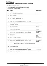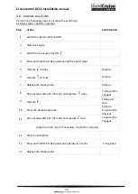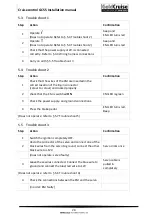
Cruisecontrol GC55 Installation manual
10
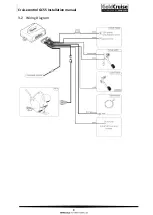
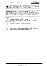
Connect the twin cable with brown and brown/white wires in such a way
that, with the brake pedal released, one wire has +12V from the brake light
fuse and the other has ground through the brake lights.
2-pin wire
lint
(blue and
black)
option 1
: connect the blue wire to the vehicle speed signal wire.
Refer to the wiring diagrams of the vehicle. Do not connect the black wire.
option 2
: connect to an (optional)
speed pulse generator on the drive shaft
or between the
speedometer cable –
connect the blue wire to the pulse
signal, connect the black wire to the speed pulse generator ground;
4-pin wire
lint
connect the waterproof connector to the servo, feed the wire lint through
the firewall to the EM, fit the 4 pins to colour (pink, blue, black, green) to
the supplied connector and connect to the EM;
8-pin
connector
connect to the 8-pin connector of the CM, also refer to the installation
manual CM
3-pin
connector
connect to the optional 3-speed memory CM (CM8).
i
Re-connect the negative battery terminal and remember to set the lost
volatile data (audio, board computer, clock, etcetera).


