background image

  Cruisecontrol GC55 Installation manual


21 

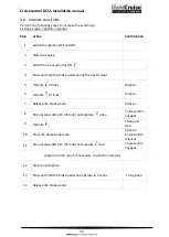
4.7


Reduce sensitivity 

Perform the following steps to increase the sensitivity.  
Perform step 1-7 within 1 minute!  

Step


Action


Confirmation


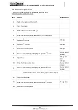
Switch the ignition OFF and ON. 


Start the engine. 


Switch the Cruisecontrol ON 


Press and hold the brake pedal during the next 2 steps 


Operate   4 times 

4 beeps 

Operate   4 times  

4 beeps 

Release the brake pedal 

4 beeps 

Drive at least 40 km/h (25 mph) and operate  

 once 

Cruisecontrol 
engages 

Operate   

1 beep per 
step 

10 

Press the brake pedal once. 

2 beeps, 
Cruisecontrol 
releases 

11 

Drive at least 40 km/h (25 mph) and operate   once 
 

Cruisecontrol 
engages 

(determine the result. If necessary, repeat from step 8.) 

12 

Stop in a safe place. 


13 

Press and hold the brake pedal and operate   4 times 

 1 long beep 

14 

Release the brake pedal. 


Summary of Contents for GoldCruise GC55

Page 1: ...Cruisecontrol GC55 Installation manual...

Page 2: ...Cruisecontrol GC55 Installation manual 1...

Page 3: ...anual supplied separately with the command module in the vehicle for the end user after completing the installation In the text boxes the following safety instructions are printed i Tip This symbol is...

Page 4: ...2 Mounting electric servo 12 3 5 Servo cable linkage 12 3 5 1 Adjusting servo cable travel 14 4 Set up 15 4 1 Introduction set up 15 4 2 Vehicle speed signal set up GC55 16 4 3 Test drive 17 4 4 Incr...

Page 5: ...on manual user manual CM included with CM installation manual CM included with CM clutch switch optional specific components servo cable pulley installation materials Depending on the modular supplies...

Page 6: ...adversely Inform the customer whenever no clutch protection is installed Point out that the GC55 will not disengage when depressing the clutch pedal John Gold advises always to install a clutch protec...

Page 7: ...can be installed in both engine bay to the body and underneath the dashboard Never mount the servo to the engine Mount the servo at least 30cm from sources of electrical interference and heat sources...

Page 8: ...ition where heat vibration and moisture are minimized such as underneath the dashboard never in the engine compartment The installation kit contains tie wraps double sided tape and screws that can be...

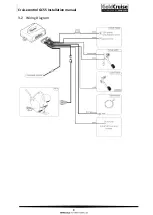
Page 9: ...Cruisecontrol GC55 Installation manual 8 3 2 Wiring Diagram...

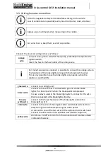
Page 10: ...wire This is only possible in case the brake lights only operate when the ignition is switched ON green wire connect to a solid ground brown wire connect to the wire that is connected to ground via t...

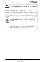
Page 11: ...generator on the drive shaft or between the speedometer cable connect the blue wire to the pulse signal connect the black wire to the speed pulse generator ground 4 pin wire lint connect the waterpro...

Page 12: ...31 38mm Yellow pulley 18 24mm 3 Secure the pulley with the M6 locking nut 4 Remove the servo inner cable 5 Shorten the servo outer cable if necessary by cutting it with sharp pliers on the servo side...

Page 13: ...bends in the servo cable have to be at least 40 cm in diameter The minimal distance between the servo cable and moving parts and the exhaust system is 30cm The servo cable has to point straight from...

Page 14: ...an be made with the following parts In case a stationary switch or kick down switch is present on the accelerator pedal the cable linkage has to be connected directly to the accelerator pedal refer to...

Page 15: ...hosen pulley In case travel A is longer than travel X 3mm adjust the cable linkage as displayed Alternatively apply a pulley with a longer travel 3 4 1 if applicable In case travel A is shorter than t...

Page 16: ...ntrol refer to 4 3 Vehicle speed signal set up Check during the test drive 4 3 the response time and sensitivity of the cruise control Only adjust the response time if the Cruisecontrol engages too sl...

Page 17: ...he brake pedal during the next 2 steps 5 Operate 4 times 4 beeps 6 Operate once 1 beep 7 Release the brake pedal 1 beep 8 Drive 70 km h and operate once Cruisecontrol engages 9 Press the brake pedal o...

Page 18: ...km h 45 mph and operate once Cruise control engages and accelerate exactly to last set cruise speed 90 km h 55 mph 9 Operate long while cruising until the speed reaches about 100 km h 65 mph CM LED tu...

Page 19: ...g the next 2 steps 5 Operate 4 times 4 beeps 6 Operate 3 times 3 beeps 7 Release the brake pedal 3 beeps 8 Drive at least 40 km h 25 mph and operate once Cruisecontrol engages 9 Operate 1 beep per ste...

Page 20: ...the next 2 steps 5 Operate 4 times 4 beeps 6 Operate 3 times 3 beeps 7 Release the brake pedal 3 beeps 8 Drive at least 40 km h 25 mph and operate once Cruisecontrol engages 9 Operate 1 beep per step...

Page 21: ...the next 2 steps 5 Operate 4 times 4 beeps 6 Operate 4 times 4 beeps 7 Release the brake pedal 4 beeps 8 Drive at least 40 km h 25 mph and operate once Cruisecontrol engages 9 Operate 1 beep per step...

Page 22: ...he next 2 steps 5 Operate 4 times 4 beeps 6 Operate 4 times 4 beeps 7 Release the brake pedal 4 beeps 8 Drive at least 40 km h 25 mph and operate once Cruisecontrol engages 9 Operate 1 beep per step 1...

Page 23: ...1 7 Press the brake pedal briefly 1 beep CM LED turns green Servo clicks once Does not operate refer to 5 7 trouble shoot 5 8 Operate 1 beep CM LED turns orange Servo clicks once Does not operate refe...

Page 24: ...ly The engine speed should now remain at a constant level 1 long beep and CM LED turns orange Does not operate refer to 5 5 trouble shoot 3 8 operate and hold until the engine speed reduces 1 long bee...

Page 25: ...colour and locked properly 2 check that the CM is switched ON CM LED is green 3 Check the power supply and ground connections 4 Press the brake pedal EM LED turns red Beep Does not operate refer to 5...

Page 26: ...check that the brown wires are connected in parallel on the brake light switch Refer to 3 3 Wiring harness connections 2 check that one of these wires has 12V and the other has ground through the bra...

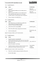
Page 27: ...er to 4 6 Increase sensitivity and 4 7 Reduce sensitivity 4 The cruisecontrol does not operate at all 1 Check if the fuse has been inserted into the fuse holder of the orange wire 2 Execute the diagno...

Page 28: ...l BV S E O Copying or distributing contents of this installation manual is only permitted with written authorisation by John Gold International BV Sales T 31 0 36 5300 886 F 31 0 36 5300 884 info john...

Reviews: