DINAMAP*
Compact
Vital Signs Monitor
39
3.3.6 Predictive Temperature Calibration
This section describes how to enter the temperature calibration code and how to calibrate the predictive
temperature circuitry. Calibration shall be conducted with an ambient temperature of 25
°
C
±
5
°
C.
Calibration of the predictive temperature is not possible without disassembling the DINAMAP*
Compact
, since adjustment of potentiometers RV2 and RV3 on the Main Board may be required.
Note:
Entry to the super service menu disables all the temperature calibration error reporting.
3.3.6.1 Calibration Requirements
I. A Counter/Timer with NAMAS approved calibration with a resolution of at least 0.1
µ
S and
an accuracy of equal or greater than 0.1
µ
S is required for set up of units with Main Board
software version earlier than 8613-V4.1.
II. A temperature calibration plug (part number 320-635) is required for the procedure, check
that the resistance between pins 1 and 2 of the temperature calibration plug is 6090
±
7
Ω
.
III. Adjustments of calibration settings must be carried out in sequence and with no
appreciable time delay between steps. This is due to the procedure being reliant on no
changes occurring to the temperature of the UUT during the set up.
IV. If UUT is a T or a TS model with Main Board software revision of 8613-V4.1 or greater,
proceed to section 3.3.6.3.
3.3.6.2 Temperature Calibration (Software revisions prior to 8613-V4.1)
I. Connect AC power adapter to UUT DC input jack socket.
II. If UUT is a Dinamap
TM
Compact T model proceed to paragraph VI.
III. Switch on UUT and enter Service Mode PIN code 2 2 1 3.
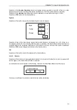
IV. Select SYSTEM from the main menu followed by SYSTEM from the sub menu.
V. Deselect the SPO
2
Option on the LCD, switch off UUT and disconnect from power source.
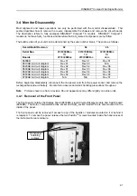
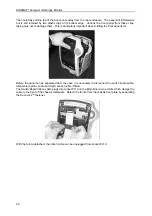
VI. Remove screws in recessed handle of the UUT and drop the front cover forward to reveal
the front chassis plate.
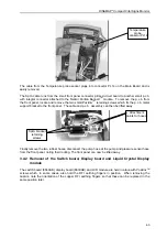
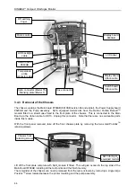
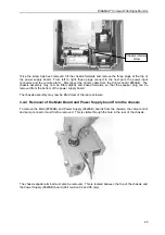
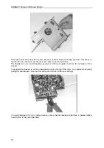
VII. With reference to Figure 1 remove clamps retaining ferrite around the Main Board to front
panel cable. Remove ferrite and unplug the front panel lead from Main Board. On TS
Model unplug SPO
2
Module to Main Board cable at the Main Board end.
VIII. With reference to Figure 1 remove two screws holding the front chassis plate to the main
chassis and remove front plate by lifting upwards. On TS Model lay front chassis plate
and SPO
2
Module to one side. Refit front panel to Main Board lead.
IX. Connect Temperature Calibration Plug to the temperature probe socket on UUT.
X. Connect Counter input high side to TP9 on Main Board connect input low side to TP6.
XI. Whilst depressing STAT, START and Alarm Mute buttons on front panel, switch on UUT.
Confirm UUT LCD is showing the Super Service Menu.
XII. Set Counter to read period of TTL square wave signal from TP9 w.r.t TP6.
XIII. Adjust RV2 on UUT Main Board to obtain a period of 3135
µ
S
±
10
µ
S. Record period for
later use.
XIV. Remove calibration resistor from UUT temperature socket.
Note:
Test paragraphs XV to XVII must be carried out immediately after the preceding paragraph.
XV. Select PTEMP from main menu.
XVI. The Counter will cycle between four distinct period readings corresponding to the O/C
probe input, 54°F, 98°F and 108° calibration points. RV3 on the Main Board must be
adjusted to set the 98° point corresponding to the period value seen on the Counter which
should be approximately 3162
µ
S. Adjust RV3 until this value is 27
µ
S
±
1
µ
S greater than
value set in paragraph XIII. Record value on history sheet.
XVII. Confirm greatest period seen on Counter is between 47.5ms to 59.0ms this value
corresponds to the 54°F calibration point.
XVIII. Turn unit off then on.

