DINAMAP*
Compact
Vital Signs Monitor
45
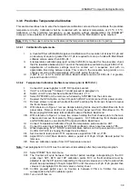
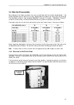
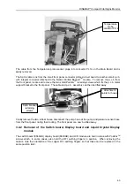
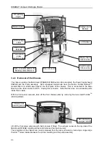
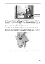
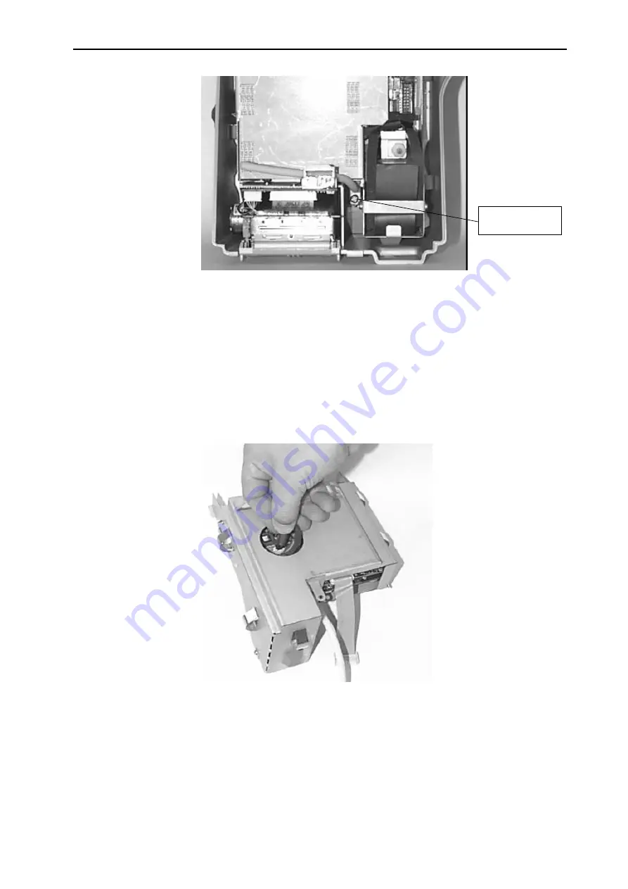
Once the screw has been removed, tilt the chassis forwards and remove the three plugs at the top of
the power supply board. From left to right, these plugs connect to the host port, the power input
connector and the remote alarm. Disconnect the printer cable from the Printer board 8650AB. The
chassis assembly may now be lifted slightly and eased forwards, so that the speaker plug can be
removed from the bottom of the power supply board.
The chassis assembly may now be lifted clear of the rear enclosure.
3.4.4 Removal of the Main Board and Power Supply board from the chassis
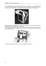
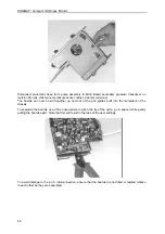
To remove the Main (8760AB) and Power Supply (8620AB) boards from the chassis, the valve control
and pump connector must first be removed. This is visible through the hole in the rear of the chassis.
The chassis spade terminal must also be removed. This is located between the top of the chassis and
the Power Supply (8620AB) board (Unit revision 04 and 06 only).
Chassis retaining
screw

