DINAMAP*
Compact
Vital Signs Monitor
52
4.2.3.1 Predictive Temperature Accuracy Check
Switch on unit.
IF UUT
°
C LED is lit, select MODE followed by SERVICE from the sub menu.
Select TEMP followed by ‘C OR F’.
When LCD displays message ‘Trend data will be lost’, select YES and confirm
°
F LED is lit.
Fit predictive oral temperature calibration plug (part no 320-635) in to unit.
Using the ROTOR control select TEMP from the main menu.
Confirm that the Temperature LED displays starting from the left, show the following sequence
‘
−
’ then ‘
−=
’, and ‘
−=≡
’.
Confirm first digit shows ‘-’ indicating an oral probe is fitted.
Confirm LED display indicate 98.6°F (+/- 0.1°F).
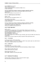
4.2.4 Pulse Oximeter Requirements
The operation of the SpO
2
module shall be tested if fitted (TS Model only). If no module is fitted
continue from section 4.2.5.
Switch on UUT.
Enter Service Mode as detailed in section 4.1.3.1
Select SYSTEM from sub menu.
Select SYSTEM from sub menu again.
If SpO
2
option box on UUT LCD does not have a tick against it, select box using rotor control, press
rotor push button and confirm it has a tick alongside it.
Switch off UUT.
4.2.4.1 Pulse data and saturation data verification
Connect a Nellcor Puritan Bennett™ Pulse Simulator either a model SRC-2, PT-2500 or N-1290 to
simulate the oximeter sensor.
Switch on UUT and allow to initialise.
Select ALARMS from main menu.
Set BPM upper limit to 250.
Set BPM lower limit to 10.
Set SpO
2
upper limit to OFF.
Set SpO
2
lower limit to 50.
Plug in Nellcor Simulator and switch on (N-1290 only).
Test DINAMAP*
Compact
unit using the full range of SpO
2
and pulse rate settings available on the
simulator to be used.
Confirm unit is within the tolerances given below.
Saturation Tolerance: 70 - 100% +2 digits
50 - 69% +3 digits
Rate Tolerance: + 3 beats per minute from 20 - 250 beats per minute.
4.2.4.2 Pulse Search verification
Set pulse rate to zero on Nellcor Puritan Bennett™ simulator (N1290 only) or disconnect simulator,
verify the "No SpO
2
Signal" message is displayed on the UUT LCD. Acknowledge message by pressing
rotor switch.
4.2.4.3 Probe Disconnected Verification

