background image

If the Draught Diverter is not accessible:

a.

Introduce smoke, by means of 

part

 of a smoke pellet on a non-combustible support, into the heat

exchanger.

b.

Extinguish the Main and Pilot burners.

c.

Ensure that there is no spillage evident by visually observing the draught diverter location on the air
heater.

d.

If spillage is evident, further investigation and rectification is required before re-testing the appliance.

WARNING: The appliance shall not be left connected to the gas supply unless it has successfully passed
the above spillage test.

6.8.3

Turn OFF the gas supply at the service cock and ensure that the Multifunctional Control fail-safe operates within
60 secs (indicated by loud click from Multifunctional Control).

6.8.4

Turn gas supply ON at service cock.

6.8.5

Switch the appliance electrical supply OFF.

6.8.6

Disconnect the fan voltage selector flying lead at the electrical control panel.

6.8.7

Switch the appliance electrical supply ON.

6.8.8

Ignite the Main and Pilot burners as detailed in sub para 6.4.1 to 6.4.8

6.8.9

Ensure that the Limit Switch operates, indicated by the Pilot and Main Burners extinguishing, within 120 and 180
seconds.

6.8.10 Switch the appliance electrical supply OFF.

6.8.11 Reconnect the fan voltage selector flying lead..

6.8.12 Switch the appliance electrical supply ON.

6.8.13 Re-ignite the Pilot burner as detailed in sub-paras 6.4.5 and 6.4.6

6.8.14 Ensure that the Main Burner re-ignites when the appliance temperature reduces, (note: with the fan having been

disconnected, there may be some delay before the Main Burner re-ignites).

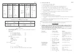
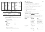
JU78

JU117

JU156

kW

MJ/h

    Btu/h

kW

 MJ/h

  Btu/h

kW

MJ/h

  Btu/h

INPUT

29.3

105.5

   100,000

43.7

157.3

  149,000

58.0

208.8

198,000

OUTPUT

22.9

82.4

   78,000

34.3

123.4

  117,000

45.7

164.5

156,000

Gas rate cv

2.78m

3

/h (98.0ft

3

/h)

4.14m

3

/h (146.1ft

3

/h)

5.49m

3

/h (194.1ft

3

/h)

1020Btu/ft

3

Burner  setting

   12.5mbar (5.0 in wg)

  12.5mbar (5.0 in wg)

   12.5mbar (5.0 in wg)

pressure (hot)

Main Injector

BRAY CAT 33/1250

Table 4

Main Burner Pressure Settings

ZZ602/6

10

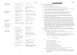
AIRFLOW (cfm)

Table 5

Fan Performance Curve

ZZ602/6

9

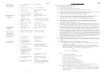
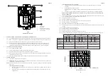
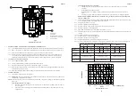
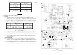
1.

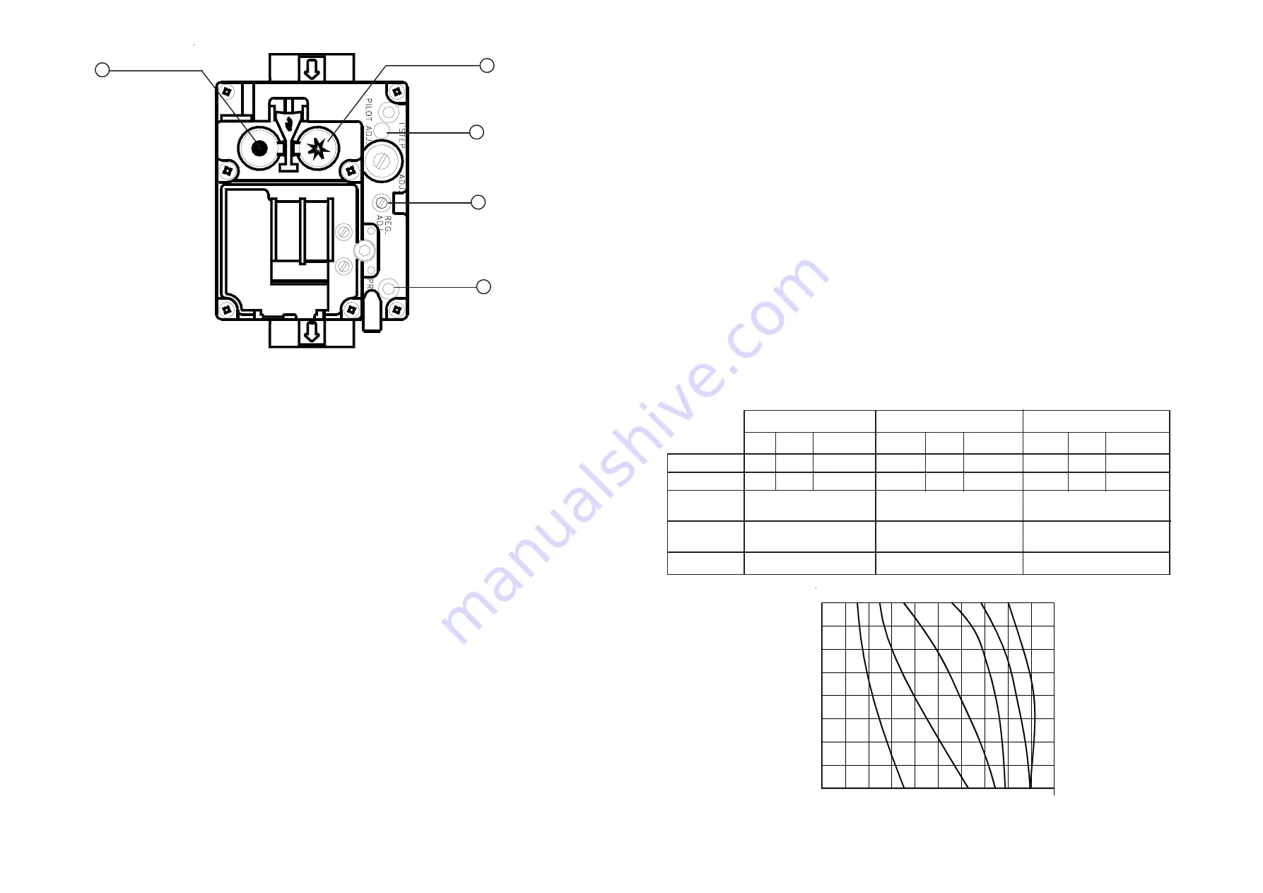
Start button

2.

Off button.

3.

Burner Pressure adjuster.

4.

Outlet Pressure test point

5.

Pilot Adjuster

  Fig. 4

Multifunctional Control

6.6

EXTINGUISHING OF BURNERS AND TEMPERATURE RISE TEST:

6.6.1

At the Multifunctional control press the OFF button and ensure that both the Main and Pilot burners extinguish.

6.6.2

Remove the pressure test gauge from the Multifunctional Control and refit the Outlet Pressure test point cover.

6.6.3

Ignite the Pilot and Main burners and allow to operate for 15 minutes to ensure stability.

6.6.4

With the main burner operating continuously, check that the temperature rise across heater is between 45

o

C -

55

o

C, setting the fan speed accordingly, (decrease fan speed to increase temperature rise). The fan speed is

adjusted by selecting the fan speed at the control panel (decrease voltage selection to decrease fan speed).

6.7

AUTOMATIC CONTROLS CHECK

6.7.1

Set the TIME CONTROL to ‘

ON

’.

6.7.2

Turn the Thermostat slowly clockwise until the Main burner ignites.

6.7.3

Ensure that the fan starts to operate after a short period (approx. 1-2 minutes).

6.7.4

When the temperature reaches the control setting, ensure that the Main burner extinguishes followed by the fan
switching off after a short period.

6.7.5

When temperature falls below control setting, ensure Main Burner re-ignites followed by fan operation.

6.8

SAFETY CHECKS:

6.8.1

Check for gas soundness within the appliance.

6.8.2

Spillage test: 

Carry out a full spillage test as follows, and ensure that the flue operates effectively with all doors

closed and any extractor fans in operation.

NOTE: 

If an extractor fan is situated in an adjoining or adjacent room, carry out the spillage test with the interconnecting

doors open.

If the draught diverter is accessible:

a.

Introduce smoke into the draught diverter adjacent to an exit from the heat exchanger, by means a smoke
match or puffer.

b.

Ensure that there is no spillage present (indicated by displacement of smoke downwards and out of the
draught diverter.

1

2

3

4

5

125

100

75

50

800

1000

1200

1400

1600

EXTERNAL

JU78,

JU78,

JU1

17,

JU1

17,

JU156,

JU156,

Summary of Contents for JU117

Page 1: ...e 2003 These instructions are to be left with the User or adjacent to the Gas Meter 1 Fig 1 General Layout Diagram 1 1 JU78 JU117 and JU156 are open flued fan assisted Upflow ducted warm air heaters the outputs of which are as follows JU78 23 0kW 82 8MJ h 78 500Btu h JU117 34 3kW 123 4MJ h 117 000Btu h JU156 45 7kW 164 5MJ h 156 000Btu h THESEAPPLIANCESCONFORMTOBS800 1 2 3 4 5 6 7 8 9 10 11 Johnso...

Page 2: ... 3A T6 3A 2 HEATER COMPARTMENTAND CLEARANCES See BS6230 2 1 When a heater is fitted into a compartment the following minimum clearances must be maintained 2 1 1 12mm 0 5in from rear and a side fitted with a blanking plate allowing extra space if a gas supply pipe enters the appliance from this side 2 1 2 600mm 24 in from a side fitted with a louvre side return panel 2 1 3 230mm 9 in from the front...

Page 3: ...e similarly insulated and in addition wrapped with a sound vapour proof barrier and protected from crushing 4 2 2 The duct system should be carefully designed as given in the guidelines in the British System Design Manual to suit the needs of its specific heating requirements and building layout The type of duct system i e radial extended plenum stepped should be installed using the least number o...

Page 4: ... The procedure is based on calculating the equivalent height of the flue under consideration i e that height of the straight vertical circular flue pipe of specific size which will produce the same flow rate as the flue under consideration The equivalent height is calculated from the formula Ki Ko e He Ha x ____________________ Ki Ko a Ke Ha Sum K where He is the height of the equivalent flue Ha i...

Page 5: ...2 x screws securing the Limit Switch and withdraw the control from the appliance 8 12 8 Refitment or replacement is in reverse order 8 13 HEAT EXCHANGERACCESS 8 13 1 Remove the upper and central front doors 8 13 2 Remove the Burner and Controls assembly as detailed in para 8 2 8 13 3 Release the 4 x securing screws and remove heat exchanger access plate and gasket from the front of the draught div...

Page 6: ... reverse order 8 8 CONTROL PANEL REMOVAL 8 8 1 Ensure that the electrical supply to the appliance is isolated 8 8 2 Release the 2 x securing screws and remove the appliance lower front door 8 8 3 At the Control Panel terminal block and referring to Fig 6 disconnect the following a 230V connections L N and E to the Air Circulating Fan at terminals 15 16 and 17 b 230V mains L N and E connections fro...

Page 7: ... except for very small rooms i e bathrooms etc Outlet faces may require partial blanking in order to achieve this 6 3 3 Set the SUMMER AIR CIRCULATION switch to OFF ZZ602 6 7 ZZ602 6 12 8 2 BURNER AND CONTROLS ASSEMBLY REMOVAL 8 2 1 Ensure that the Gas and Electrical supplies are switched OFF 8 2 2 Remove the appliance central front door 8 2 3 Disconnect the Multifunctional Control and Limit Switc...

Page 8: ...switches and summer air circulation switch and that the time control if fitted must be reset following a power failure 7 2 3 How to extinguish the pilot and main burner at the Multifunctional control and switch off electrical supply to the heater 7 2 4 How to remove clean and re fit the air filter if fitted and at what intervals i e fortnightly or weekly for new premises 7 2 5 How to control the h...

Page 9: ...er Pressure Settings ZZ602 6 10 AIRFLOW cfm Table 5 Fan Performance Curve ZZ602 6 9 1 Start button 2 Off button 3 Burner Pressure adjuster 4 Outlet Pressure test point 5 Pilot Adjuster Fig 4 Multifunctional Control 6 6 EXTINGUISHING OF BURNERS AND TEMPERATURE RISE TEST 6 6 1 At the Multifunctional control press the OFF button and ensure that both the Main and Pilot burners extinguish 6 6 2 Remove ...

Page 10: ...er Pressure Settings ZZ602 6 10 AIRFLOW cfm Table 5 Fan Performance Curve ZZ602 6 9 1 Start button 2 Off button 3 Burner Pressure adjuster 4 Outlet Pressure test point 5 Pilot Adjuster Fig 4 Multifunctional Control 6 6 EXTINGUISHING OF BURNERS AND TEMPERATURE RISE TEST 6 6 1 At the Multifunctional control press the OFF button and ensure that both the Main and Pilot burners extinguish 6 6 2 Remove ...

Page 11: ...switches and summer air circulation switch and that the time control if fitted must be reset following a power failure 7 2 3 How to extinguish the pilot and main burner at the Multifunctional control and switch off electrical supply to the heater 7 2 4 How to remove clean and re fit the air filter if fitted and at what intervals i e fortnightly or weekly for new premises 7 2 5 How to control the h...

Page 12: ... except for very small rooms i e bathrooms etc Outlet faces may require partial blanking in order to achieve this 6 3 3 Set the SUMMER AIR CIRCULATION switch to OFF ZZ602 6 7 ZZ602 6 12 8 2 BURNER AND CONTROLS ASSEMBLY REMOVAL 8 2 1 Ensure that the Gas and Electrical supplies are switched OFF 8 2 2 Remove the appliance central front door 8 2 3 Disconnect the Multifunctional Control and Limit Switc...

Page 13: ... reverse order 8 8 CONTROL PANEL REMOVAL 8 8 1 Ensure that the electrical supply to the appliance is isolated 8 8 2 Release the 2 x securing screws and remove the appliance lower front door 8 8 3 At the Control Panel terminal block and referring to Fig 6 disconnect the following a 230V connections L N and E to the Air Circulating Fan at terminals 15 16 and 17 b 230V mains L N and E connections fro...

Page 14: ...2 x screws securing the Limit Switch and withdraw the control from the appliance 8 12 8 Refitment or replacement is in reverse order 8 13 HEAT EXCHANGERACCESS 8 13 1 Remove the upper and central front doors 8 13 2 Remove the Burner and Controls assembly as detailed in para 8 2 8 13 3 Release the 4 x securing screws and remove heat exchanger access plate and gasket from the front of the draught div...

Page 15: ... The procedure is based on calculating the equivalent height of the flue under consideration i e that height of the straight vertical circular flue pipe of specific size which will produce the same flow rate as the flue under consideration The equivalent height is calculated from the formula Ki Ko e He Ha x ____________________ Ki Ko a Ke Ha Sum K where He is the height of the equivalent flue Ha i...

Page 16: ...e similarly insulated and in addition wrapped with a sound vapour proof barrier and protected from crushing 4 2 2 The duct system should be carefully designed as given in the guidelines in the British System Design Manual to suit the needs of its specific heating requirements and building layout The type of duct system i e radial extended plenum stepped should be installed using the least number o...

Page 17: ... 3A T6 3A 2 HEATER COMPARTMENTAND CLEARANCES See BS6230 2 1 When a heater is fitted into a compartment the following minimum clearances must be maintained 2 1 1 12mm 0 5in from rear and a side fitted with a blanking plate allowing extra space if a gas supply pipe enters the appliance from this side 2 1 2 600mm 24 in from a side fitted with a louvre side return panel 2 1 3 230mm 9 in from the front...

Page 18: ...e 1 1 1 9 397819 BOS02394 Electrode lead 1 1 1 10 U780 0700000 Burner and Controls Assembly 1 U117 0700000 Burner and Controls Assembly 1 U560 0700000 Burner and Controls Assembly 1 11 U780 0752000 Main Burner 2 3 4 12 1000 0703720 Main Injector BRAYCat 33 1250 2 3 4 13 BOS01676 4 Cross Lighting Injector InterAlbion T100 1 1 14 S00461 Heat Exchanger exchange kit 1 S00462 Heat Exchanger exchange ki...

Page 19: ...e 2003 These instructions are to be left with the User or adjacent to the Gas Meter 1 Fig 1 General Layout Diagram 1 1 JU78 JU117 and JU156 are open flued fan assisted Upflow ducted warm air heaters the outputs of which are as follows JU78 23 0kW 82 8MJ h 78 500Btu h JU117 34 3kW 123 4MJ h 117 000Btu h JU156 45 7kW 164 5MJ h 156 000Btu h THESEAPPLIANCESCONFORMTOBS800 1 2 3 4 5 6 7 8 9 10 11 Johnso...

Reviews: