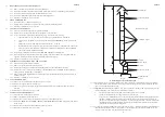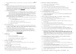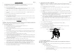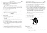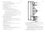
5.1.15 Special consideration must be given to external flues with a view to prevention of condensation and weathering
problems.
5.2
ELECTRICAL
5.2.1
Mains.
A single phase 230V 50Hz mains connection from a fused spur, rated at 13A with a double pole switch
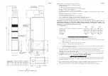
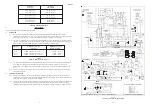
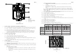
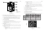
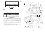
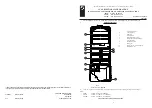
for isolation is required for the installation. Location of connections is shown at Fig. 5. Mains may be brought
into the appliance via the electrical entry holes on either side, 600mm above the floor. A cable clamp with 2 self
tapping screws is provided to secure the mains cable adjacent to the entry hole, using the 2 screw holes provided.
All wiring must be to I.E.E regulations for electrical installations, using heat resisting 3 core cable to BS 6500
WARNING: TERMINALS MARKED ‘0V’ ARE NOT EARTH.
5.2.2
Thermostat and its location.
a.
A 24V thermostat which complies with BS 800, BS 3955 and BS 4201 must be supplied and is essential to
ensure close control of the comfort level. An anticipator is located in the thermostat which is rated in
amps. The current rating of the anticipator should correspond with the current rating of the multifunctional
control, (i.e. 0.6A). The anticipator should be checked and adjusted as necessary. Connection to the air
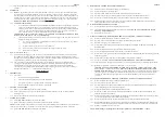
heater is as shown in Fig. 5, using sheathed conductors compliant with BS6500.
IMPORTANT: When a thermostat is fitted to the installation, ENSURE THAT THE BLUE LINK
WIRE between terminals ‘8’ and ‘11’ IS REMOVED.
b.
The Thermostat should be located where there is free air circulation approx. 1.5m (5ft) from the floor, and
avoiding the following locations:-
i)
In a room where temperature is greatly affected by the sun or any other heat source, (e.g. radiant
fire, wall light fittings or TV set).
ii)
Near an outside door or windows, or on an outside wall.
iii)
Where affected by warm air ducts, diffusers, waste pipes or the heater itself.
iv)
Where subject to vibration.
5.3
GAS
(See BS5864 and BS6891)
5.3.1
An independent gas supply pipe from the meter is to be preferred wherever possible. When this is not possible,
the pipe must be capable of taking the complete input of the heater and all other gas appliances being served by
this same pipe. This supply should be suitably sized to conform to British Standards requirements of no more than
1.0 mbar (0.4in wg) pressure drop (See table of discharge in BS6891).
5.3.2
The
3
/
4
in union gas cock (supplied) must be fitted to the gas inlet of the heater for easy isolation during
servicing. The gas pipe should be so fitted and installed as to be durable, substantial and gas tight. To assist in
determining where a gas connection may not be tight, a leak detection fluid should be applied around the
connection. Under no circumstances should a flame be used to locate a gas leak. Gas entry to the air heater is
through either side to a Rc
3
/
4
(
3
/
4
in BSP. external [taper] thread).
6.
COMMISSIONING
6.1
PREPARATION:
6.1.1
Ensure that:
a.
Gas and Electrical supplies are
OFF.
b.
Filter, fan and fan compartments are free from obstructions.
c.
All registers or grilles are open and conform to design specifications.
d.
Return, relief and ventilation air installations are adequate.
6.2
SETTING OF FAN SPEED:
6.2.1
Remove the fan chamber door and the air filter (if fitted).
6.2.2
Set the Fan Speed selector to 230V for heaters fitted to ducted installations, or 210V for heaters utilizing
discharge heads.
6.2.3
Refit the fan chamber door and air filter (if required).
6.3
SYSTEM BALANCING:
6.3.1
Set the SUMMER AIR CIRCULATION switch to ‘
ON
’.
6.3.2
Balance the system to provide required volume proportions at warm air outlets.
NOTE:
If system includes ceiling diffusers, air velocities through these should be NOT LESS THAN 1.5m/s (300ft/min),
except for very small rooms (i.e. bathrooms etc.). Outlet faces may require partial blanking in order to achieve this.
6.3.3
Set the SUMMER AIR CIRCULATION switch to ‘
OFF
’.
ZZ602/6
7
ZZ602/6
12
8.2
BURNER AND CONTROLS ASSEMBLY REMOVAL:
8.2.1
Ensure that the Gas and Electrical supplies are switched OFF
8.2.2
Remove the appliance central front door.
8.2.3
Disconnect the Multifunctional Control and Limit Switch electrical connections.
8.2.4
Disconnect the gas supply by breaking the union at the input side of the Multifunctional Control.
8.2.5
Remove the 4 x Burner assembly fixing screws and withdraw the Burner and Controls Assembly.
8.2.6
Refit Burner and Controls Assembly in reverse order, ensuring that the Multifunctional Control leads pass
through the grommet on the burner mounting bracket.
8.3
MAIN BURNER ASSEMBLY CLEANING:
8.3.1
Remove the Burner and Controls assembly as detailed in 8.2.
8.3.2
Clean the burner thoroughly both inside and out with a soft brush.
DO NOT ENLARGE, DISTORT OR
DAMAGE BURNER HOLES.
8.3.3
Reassemble in reverse order.
8.4
MAIN INJECTORS AND BURNER ARMS, REMOVAL, CLEANING AND REPLACEMENT:
8.4.1
Remove the Burner and Controls Assembly as details in 8.2.
8.4.2
Disconnect the Thermocouple and Pilot Feed Pipe at the Multifunctional Control.
8.4.3
Disconnect the Igniter Lead at the Piezo Unit.
8.4.4
Release the 4 x screws and nuts securing the Burner Assembly, and withdraw the Burner Assembly from the
Burner Manifold.
8.4.5
Release the Main Injectors from their housings in the Burner Assembly.
8.4.6
Release the Crosslighting Injector from its housing in the Burner Assembly.
8.4.7
Release the 3 x screw and nuts securing each main burner and the Crosslighting Burner to the mounting plate, and
withdraw each burner.
8.4.8
Release the 2 x securing screws and nuts, and withdraw the Pilot Burner Assembly.
8.4.9
Clean as necessary.
DO NOT ENLARGE, DISTORT OR DAMAGE MAIN INJECTOR HOLES.
8.4.10 If the injectors are to be replaced, ensure that they are correctly marked, referring to the Data Badge for details.
8.4.11 Refitment or replacement of injectors or burner arms is in reverse order.
Important:
DO NOT OVER-TIGHTEN the Thermocouple connection. Tighten to finger tight + 1 flat.
Burners should be cleaned with a soft brush.
Under no circumstance should the burner holes be enlarged,
distorted or brushed strongly.
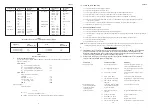
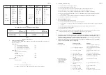
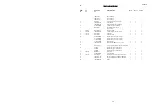
If an injector is replaced, ensure that is correctly marked, referring to Table 4 or
short list of spares. After replacement or refitment of the Pilot Burner, ensure that the gap between the igniter
electrode and the Pilot Burner tip is approximately 3mm, and that the flame profile is correct, adjusting as
necessary.
8.5
PILOT BURNER, THERMOCOUPLE AND ELECTRODE, REMOVAL AND REPLACEMENT:
8.5.1
Remove the Burner and Controls Assembly as detailed in 8.2
8.5.2
Disconnect Igniter lead from Piezo unit.
8.5.3
Disconnect the Thermocouple from the Thermocouple adapter on the Multifunctional Control, taking care to
avoid causing damage to the Thermocouple Capillary.
8.5.4
Release the Pilot Feed Pipe from the Multifunctional Control.
8.5.5
Remove the 2 x 4mm screws securing the Pilot Burner Assembly to the Burner and Control Assembly, and
withdraw the Pilot Burner Assembly.
8.5.6
Release the Thermocouple securing nut from the Pilot Burner Assembly and withdraw the Thermocouple, taking
care to avoid causing damage to the Thermocouple Capillary.
8.5.7
Release the Electrode securing nut from the Pilot Burner Assembly and withdraw the Electrode.
8.5.8
Release the Pilot Feed Pipe securing nut from the Pilot Burner Assembly and withdraw the Pilot Feed Pipe and
Pilot Injector from the Pilot Burner Assembly, and disconnect the Pilot Injector from the Pilot Feed Pipe hook.
8.5.9
Refitting or replacement is in reverse order.
NOTE: When refitting or replacing the Thermocouple, tighten only to FINGER TIGHT + 1 FLAT.


