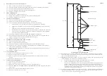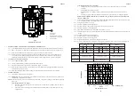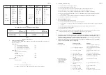
Position of
Air direct
Air Vents
from outside
JU78 - High Level
132 cm
2
(21 in
2
)
JU78 - Low Level
264 cm
2
(42 in
2
)
JU117 - High Level
197 cm
2
(31 in
2
)
JU117 - Low Level
393 cm
2
(62 in
2
)
JU156 - High Level
261 cm
2
(41 in
2
)
JU156 - Low Level
522 cm
2
(82 in
2
)
Table 1: Minimum Effective Areas
4.
DUCT SYSTEM
(See British Design Manual - Gas fired Warm Air Heating)
4.1
RETURN AIR
4.1.1
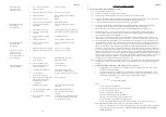
If the air heater is installed in a compartment, all return air shall be POSITIVELY ducted from outside the
compartment to the bottom of the unit. It is recommended that the return air duct be not routed directly from the
main occupied area, but from a convenient central area serving the remainder of the building.
4.1.2
The return air system must be constructed of non-combustible material. The flue shall not be run through an area
serving as a return air path. It is extremely important that the correct size of return air grilles and ducting is used.
Return air duct sizes and minimum open areas of return air grilles are as listed in Table 2.
Appliance
Minimum return air
Minimum free area of
duct size
Return air grilles
JU78
300mm x 300mm ( 12 in x 12 in )
1887cm
2
(291 in
2
)
JU117
450mm x 300mm ( 18 in x 12 in )
2796cm
2
(434 in
2
)
JU156
600mm x 300mm ( 24 in x 12 in )
3725cm
2
(578 in
2
)
Table 2
Minimum Return Air and Free Area
4.1.3
An adequate and unobstructed return air path is essential from areas not served by a directly ducted return and to
which warm air is delivered. All such rooms should be fitted with relief grilles which have a free area of
0.0088m
2
/kW (1in
2
/250Btu/h) of heat supplied to the room. The only exceptions are kitchens, bathrooms and
WC.’s.
4.1.4
All duct work in the room or internal space in which the heater is installed shall be mechanically secured, and
sealed with ducting tape.
4.2
WARM DELIVERED AIR
4.2.1
All duct work, including riser ducts, should be fully insulated with 50mm (2in) fibreglass or similar. If short
extended duct runs are taken below floor level these should be similarly insulated, and in addition wrapped with a
sound vapour proof barrier, and protected from crushing.
4.2.2
The duct system should be carefully designed (as given in the guidelines in the British System Design Manual) to
suit the needs of its specific heating requirements and building layout. The type of duct system, (i.e. radial/
extended plenum/stepped) should be installed using the least number of fittings to minimise airflow resistance.
3
ZZ602/6
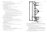
16
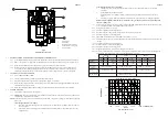
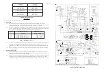
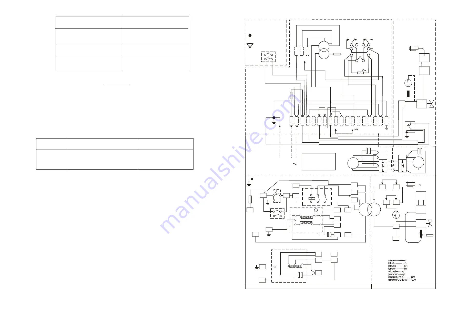
Fig. 5
JU Series Air Heaters Wiring Diagram
N
16
5
7
v
TAP
r
br
T4
9
WARNING
7 AND 9 ARE
OV
DO NOT EARTH
11
T1
T2
8
y
y
A
B
p/r
p/r
1.6A
6.3A
N/C
5
3
1.6A
TRANSFORMER
6
7
2
1
8
br
b
OV
24V
240V
FAN
210V
PWR
L
N
br
br
b
b
br
g/y
br
br
240V
FAN VOLTS
SELECTOR
EQUIPOTENTIAL
BONDING POINT
SUMMER
SWITCH
THESE ITEMS IN
BURNER CHAMBER
FLOOR
WARNING
DO NOT CONNECT
TO EARTH
4
N/C
N/O
240V
210V
N/O
bk
bk
6
24V
24V
GAS
PILOT
THERMO
COUPLE
GAS
CONTROL
INTERRUPTOR
UNIT
O’HEAT
LIMIT
CONTROL
AIR
TEMPERATURE
PROBE
THESE ITEMS MOUNTED
ON FRONT BULKHEAD
GAS
CONTROL
LIMIT
SWITCH
O’HEAT
LIMIT
CONTROL
AIR TEMP.
PROBE
INTERRUPTOR
UNIT
LIMIT
SWITCH
JU156
ONLY
N
NC
Wire colour code where indicated
LABEL REF NO 1000-2205540-02
CIRCUIT DIAGRAM: JU78, JU117 AND JU156 AIR HEATERS
y
MAIN
AUX
WINDINGS
FAN MOTOR
JU156 C1=16uF
WARNING:
THERMOSTAT
CIRCUIT
IS 24V
NOT MAINS
JU117 C1=7uF
JU117 & JU156
JU78
JU156
ONLY
15
20
19
18
15
L
16
N
L
F1
F2
14
240v
LO
210V
240V
HI
NC
NC
N
16
17
N
L
17
g/y
b
br
b
b
b
b
b
g/y
g/y
br
br
br
r
br
br
br
6.3A
DIRECT EARTH
POINT (DEP)
br
br
C1
Z2
U1
br
br
br
6
2
b
7
8
1
3
17
br
y
BUTT
CONNECTOR
bk
IN
g/y
b
OUT
THIS SIDE
16
15
14
13
12
11
10
9
8
2 CORE CABLE
3 CORE CABLE
7
6
5
LINK A
4
F
2
NC
OV
T2
NC
T1
NC
240V
FAN
PWR
L
N
NC
y
bk
y
r
SL
EE
V
E T
H
IS
E
N
D
br
LINK B
T4
OV
24V
GAS
CONTROL
FAN
SW
1
F
N
19
20
L
br
g/y
g/y
DIRECT EARTH
POINT
br
y
v
y
bk
p/r
br
br
br
br
br
br
br
b
br
r
br
p/r
b
b
18
Z1
U2
OL
AUX. WINDING
MAIN WINDING
FAN MOTOR
RELAY
SUMMER
SWITCH
FAN
CONTROL
24V
0V
S
L
N
P
FAN
MOTOR
FAN
CONTROL
FAN
MOTOR
P
S
T
JU78
JU117
AND
JU156
8uF
LINKS A AND B
A: REMOVE WHEN USING VOLT
FREE TIMED OR MANUAL
SWITCH.
B: REMOVE WHEN USING
THERMOSTAT.
SUPPLY 240V
50 Hz
FUSED 13A

