background image

22

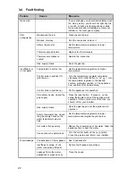
Failure

Cause

Measure

3.4

Fault finding

Blocked pilot burner

Blocked chimney

Safety thermostat

Thermocouple defective

Thermocouple makes no
contact

Gas supply closed

Temperature is set too low

Control knob in position (

)

(pilot burns )

Control knob in position (

)

Flue safety device closed the
gas supply

Gas supply closed

Safety thermostat has closed
the gas supply because the
water temperature was too
high

Hot water storage empty

Cause cannot be determined

Condensation of (flue) gasses

Insufficient sealing of the
water connections (thread)

Leakage from other water-
appliances or pipes near by

Gas smell

Pilot
extinguishes

Insufficient or
no hot water

Water leakage

If you smell gas you should immediately close
the main gas tap  you should not light any fire
or switch on light, electrical switches or bells.
Open windows and immediately contact your
installer or the local gas company.

Clean the pilot burner

Find the cause and remove it.

Set the temperature regulator at a lower
temperature.

Replace the thermocouple

Restore the connection

Open the gas tap

Set the temperature regulator at a higher
temperature

Turn the temperature regulator completely
clockwise; turn control button to “on” ( 


) ; turn

the temperature regulator to the desired
position, preferably position 4. The appliance
now operates fully automatically.

Put the appliance into operation.

Press the reset button - if present - on the
safety thermostat and put the appliance into
operation. If this occurs more often then you
should inform your installer.

Open the gas tap and put the appliance into
operation.

Set the temperature regulator at a lower
temperature and reignite the pilot burner.

Reduce the consumption of hot water. Allow the
appliance time to heat the water.

Turn the control button to the (

) position.

Close the gas tap and inform your installer.

See “Condensation”.

Tighten the threaded connections.

Trace the cause.

Summary of Contents for SCT 100-95 G

Page 1: ...1 SCT 75 75 G SCT 100 95 G WATERSTORAGEHEATERS UNITED KINGDOM IRELAND MODEL INSTALLATION AND USER INSTRUCTIONS...

Page 2: ...ly harm Installation and commissioning should be carried out by a qualified competent installer The type of gas and the value at which the appliance is set standard in the factory are registered on th...

Page 3: ...13 2 1 5 Draught diverter 13 2 2 Commissioning 14 2 3 Pilotadjustment 15 2 4 Putting out of operation 15 2 5 Temperature regulation 15 2 6 Setting the nominal heat input 16 2 7 Conversion procedure 1...

Page 4: ...Draught diverter 2 Hot water outlet 3 Insulation material 4 Flue tube 5 Glass lined tank 6 Gas control valve 7 Cold water inlet pipe 8 T P safety connection 9 Steel jacket 10 Flue baffle 11 Sacrifici...

Page 5: ...y heat loss When the appliance is filled with water it continuously is under water pressure As hot water is drained from the tank cold water is added immediately Four flue baffles have been placed in...

Page 6: ...imum inlet pressure is 50 mbar Flue down draught safety device The heater is fitted with a flue gas blowback safety device The functioning of the safety device is based upon the principle of the Therm...

Page 7: ...ffers from down draught conditions We advice that necessary remedial actions be carried out by a competent person Important If the water heater is put out of operation by a failure this may be caused...

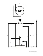
Page 8: ...announced diameter dimension G All dimensions are given in mm rounded off on 5 mm A 1585 1780 B 1450 1640 D 645 675 E 735 765 G 130 130 K 375 375 M 1505 1685 N 1505 1685 R 285 285 S 1280 1460 1 Cold w...

Page 9: ...9 Drawing 3 Dimensions...

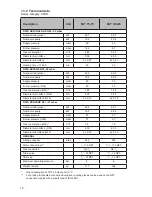
Page 10: ...er main orifice G30 mm 2 30 2 35 Diameter pilot orifice G30 mm 2 x 0 16 2 x 0 16 DATA PROPANE G31 37 mbar Nominal load gross kW 24 6 26 1 Nominal capacity kW 19 2 20 4 Supply pressure mbar 37 37 Burne...

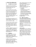
Page 11: ...nt Installation should be carried out in accordance with all local authority and building regulations local water authority and fire regulations and the following British standards 5440 5546 6644 6700...

Page 12: ...n an unvented cold water supply system a kit of valves and fittings listed by the water research centre and complying with part G3 of the current building regulations should be used Installation shoul...

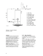
Page 13: ...lvanised and must include a tested and approved terminal to BS 5440 part I If the flue passes through any combustible material measures must be taken to protect against the possibility of fire All flu...

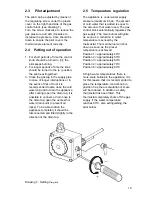
Page 14: ...emove the outer door of the combustion chamber 4 Keep the control knob pushed in and press the piezo ignitor several times until the pilot burns see drawing 6 5 Keep the control button pushed in for a...

Page 15: ...To be able to drain the appliance completely it should be disconnected and tilted slightly in the direction of the drain tap 2 5 Temperature regulation The appliance is under water supply pressure max...

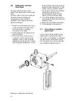
Page 16: ...adjustment see drawing 8 To make this possible the temperature control knob should be removed by pulling it straight forward making the pr adj visible Turning clockwise reduces the pressure turning an...

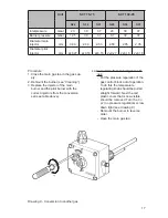
Page 17: ...e temperature regulating knob should be pulled straight forward Next the red plastic cover that is now visible should be removed Turn the no pr no pressure regulation screw down tight see drawing 9 Re...

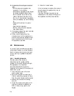
Page 18: ...water heater it is recommended that it is cleaned and serviced at least once a year by a qualified competent person 2 8 1 Sacrificial anode The life cycle of the anode is determined by the quality and...

Page 19: ...cleaning of the pilot and main burner the operation of these should be checked If necessary the burner pressure of the main burner should be reset 2 8 3 Decalcification Formation of lime scale depend...

Page 20: ...ether there are any leaks or open taps 4 Is the gas supply adequate Check and correct if necessary 5 Perhaps the hot water consumption is higher than was originally calculated 6 Check whether the cold...

Page 21: ...that is added is equal to the amount of hot water used The gas control block automatically regulates the gas supply The main burner will ignite as soon as a reduction in water temperature is sensed by...

Page 22: ...ontact your installer or the local gas company Clean the pilot burner Find the cause and remove it Set the temperature regulator at a lower temperature Replace the thermocouple Restore the connection...

Page 23: ...nd or energy inputs which do not exceed those stated on the rating plate of the water heater d in a non corrosive atmosphere or area e with an approved temperature and pressure relief valve of adequat...

Page 24: ...eater as suitable for purpose except within the terms of warranty detailed above STATE WATER HEATERS will not be liable by virtue of this guarantee or otherwise for damage to any persons or property w...

Page 25: ...25...

Page 26: ...26...

Page 27: ...27...

Page 28: ...28 0308 254 R1...

Reviews: