background image

Minerals that are naturally found in water cause the water to 
be electrically conductive . Water conductivity is measured in 
micro Siemens per centimeter (uS/cm) . Mineral content, also 
described as “water hardness” is usually measured in grains per gallon . Because of the variety of minerals that are found in water, there is no 
direct correlation between water hardness and conductivity, but generally the higher the mineral content, the higher the conductivity . 
The Canister Steam Humidifier is designed to operate on water with conductivity between 125 and 1,250 uS/cm . This correlates loosely with 
water with hardness between 3 and 36 grains/gallon . Water that is considered “hard” and also softened water work well in the humidifier . The 
humidifier will make steam when plumbed to low-conductivity water but it takes longer to reach nominal capacity . 

with low conductivity water, it may take the humidifier one week or more of operation to reach rated capacity, especially if it 
is wired to operate on 120 volts. when operating on 240 volts, the humidifier usually will reach nominal capacity within a few 
hours, even with lower conductivity water. 

As water in the canister boils and turns into steam, minerals are left behind . The remaining minerals, if they remain in solution in the water, 
increase the conductivity of the water . Minerals also deposit onto the submerged portions of the electrodes rendering those areas ineffective . As 
this occurs, the level of water in the canister rises to expose uncoated electrode surface .

SPeCIfICaTIonS & DIMenSIonS

Table 1 – Specifications 

Voltage

kw

Maximum steam capacity

nominal Current draw (amps)

Humidifier unit operating weight

gal/day

amps

lbs

120V

1 .4

11 .5

11 .5

23

208V

2 .4

20 .5

11 .5

23

240V

2 .8

23 .3

11 .5

23

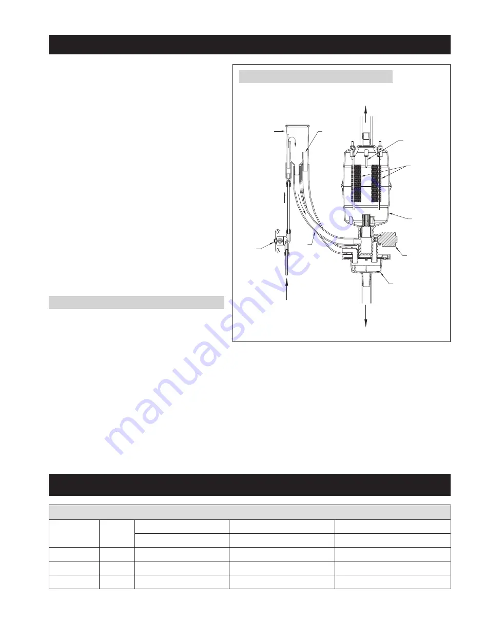
The Canister Steam Humidifier delivers humidity in the form 
of steam to the conditioned space via the HVAC system 
duct or optional Fan Pack . The humidifier generates steam 
by energizing two electrodes that extend into a canister 
of water . Current flowing between the electrodes causes 
the water to boil, creating steam . Water is introduced to 
the humidifier through a fill valve to a fill cup located in 
the top of the cabinet . The fill cup serves as an overflow 
reservoir and provides an air gap between the humidifier 
and water source . The steam canister is filled from the 
bottom . The canister is seated in a drain cup assembly 
which includes a drain valve . The drain and fill valves work 
together to maintain water level in the canister to deliver 
the rated steam capacity based on the electrical conductivity 
of the water and to temper drain water . See 

figure 1

 for 

representation of fill and drain system and canister . 
Steam is delivered into the airstream through a dispersion 
tube mounted in the HVAC system ductwork . Openings in the 
dispersion tube are fitted with “tubelets” which extend into 
the center of the tube . The design of the dispersion tube and 
tubelets distribute steam over a wide area in the duct and 
direct any condensed moisture back into the steam hose .

PRInCIPleS of oPeRaTIon

fIGURe 1 – fill and Drain System and Canister

90-1522


Steam

Outlet

Drain

Supply

Water

Drain Cup

Drain Valve

Canister

Electrodes

High Water

Level Sensor

Flow Control

Orifice

Inlet

Fill Valve

Overflow

Fill

Fill Cup

waTeR QUalITy

3

Summary of Contents for 8000 Residential Steam Humidifier

Page 1: ...l Power Wiring Shut off Switch 10 Start up Procedure 14 Sequence of Operation 14 Operating Modes 15 Shut Down Procedure 15 Display Panel 16 Maintenance 17 Checking System Operation Troubleshooting 18 Replacement Parts 21 READ AND SAVE THESE INSTRUCTIONS Model 8000 Residential Steam Humidifier Installation Maintenance Instructions Johnson Controls Unitary Products Subject to change without notice P...

Page 2: ...erforming service or maintenance procedures on any part of the humidification system Failure to disconnect electrical power could result in fire electrical shock and other hazardous conditions These hazardous conditions could cause property damage personal injury or death Contact with energized circuits can cause property damage severe personal injury or death as a result of electrical shock or fi...

Page 3: ...ensions Table 1 Specifications Voltage kW Maximum steam capacity Nominal Current draw amps Humidifier unit operating weight gal day amps lbs 120V 1 4 11 5 11 5 23 208V 2 4 20 5 11 5 23 240V 2 8 23 3 11 5 23 The Canister Steam Humidifier delivers humidity in the form of steam to the conditioned space via the HVAC system duct or optional Fan Pack The humidifier generates steam by energizing two elec...

Page 4: ...5 3 4 Dispersion Outlet Electrical Knockouts Fill Cup TOP VIEW 7 1 8 SIDE VIEW 1 4 4 12 BACK VIEW Mounting Holes 3 3 8 7 7 8 2 3 3 8 Water Fill Line Connection Drain BOTTOM VIEW 3 sq 2 sq 8 1 4 1 dia STEAM DISPERSION TUBE 3 Mounting Plate to first opening 1 3 4 UP 90 1701 Specifications Dimensions continued 4 ...

Page 5: ...ection in the duct The plate is labeled UP to indicate proper orientation If the dispersion tube is mounted on insulated ductwork make sure insulation is not more than 2 thick at tube location to prevent insulation from blocking first steam outlet Note If two dispersion tubes are installed in one duct double the dispersion distances If three dispersion tubes are installed triple the dispersion dis...

Page 6: ...equired see note 1 Drip tee installation for piping over obstruction or if dispersion tube is lower than humidifier NOTES 1 Refer to governing codes for drain pipe size and materials 2 Support steam hose so there are no sags or low spots Drip tee Drain trap Figure 4 Dispersion Tube Mounted Below Humidifier 90 1703 Elevation The preferred location for the dispersion tube is higher than the humidifi...

Page 7: ...ows how capacity is reduced as the distance between the humidifier and dispersion tube increases If the humidifier is mounted on the duct directly below the dispersion tube allow space for a bend in the steam hose The humidifier can be mounted to a wood surface or to sheet metal ductwork if it is structurally stable Do not mount humidifier to fiber duct board The humidifier must be mounted to a ve...

Page 8: ...l is visible Reattach the electrode conductors interchangeable and the high water level sensor wire INSTALL Steam Dispersion TUBE Note If humidifier will deliver steam via a Fan Pack instead of the dispersion tube follow instructions included with Fan Pack Make sure steam dispersion tube is mounted higher than the humidifier so that condensate that forms in the tube runs back into the canister If ...

Page 9: ...MOVE WIRE G TO G HIGH HUMIDITY LIMIT SWITCH OPTIONAL NOTES 1 18AWG WIRE IS ACCEPTABLE FOR 24V INSTALLATIONS 2 FAN PACK TERMINALS PROVIDE 24 VAC ON CALL FOR HUMIDITY AND REMAIN ENERGIZED FOR TWO MINUTES AFTER CALL IS SATISFIED BLUE NC ORANGE NO YELLOW C WHITE YELLOW WHITE BLUE FAN PACK HUMIDISTAT CANISTER STEAM HUMIDIFIER OPTIONAL HIGH HUMIDITY LIMIT SWITCH OUTDOOR TEMPERATURE SENSOR 24 VAC SOURCE ...

Page 10: ...ntact with energized circuits can cause property damage or severe personal injury Wiring Instructions Install disconnect switch not provided between line power source and humidifier Knock outs for power wiring and low voltage control circuit wiring are located on the top of the humidifier Connect power and ground wiring as shown in appropriate wiring diagram 240 VAC Figure 8 208 VAC Figure 9 120 V...

Page 11: ...4V DC J11 2 J11 1 J13 2 J13 1 J12 2 J12 1 STEAM CYLINDER J3 2 J3 1 J1 2 1 0 L1 N L2 TERMINAL BLOCK BLK BLK 4 2 6 8 24V AC YEL BLU CONTROL PCB CURRENT SENSING PCB J1 1 HUMIDIFIER CONTROL HIGH LEVEL PROBE OPTIONAL FAN PACK 24V AC COM HUMIDISTAT FAN BLK YEL YEL POWER RELAY CONTACTS PROBE J4 J2 J10 2 DISPLAY PANEL RIBBON CABLE GROUND TRANSFORMER 75VA 208 240 120 WHT BLK WHT RED ORG BLK VIO UNUSED 480V...

Page 12: ...08 240 VAC SAFETY SWITCH BLU 24V DC 24V DC J11 2 J11 1 J13 2 J13 1 J12 2 J12 1 STEAM CYLINDER J3 2 J3 1 J1 2 1 0 L1 N L2 TERMINAL BLOCK BLK BLK 4 2 6 8 24V AC YEL BLU CONTROL PCB CURRENT SENSING PCB J1 1 HUMIDIFIER CONTROL HIGH LEVEL PROBE OPTIONAL FAN PACK 24V AC COM HUMIDISTAT FAN BLK YEL YEL POWER RELAY CONTACTS PROBE J4 J2 J10 2 DISPLAY PANEL RIBBON CABLE GROUND TRANSFORMER 75VA 208 240 120 WH...

Page 13: ...08 240 VAC SAFETY SWITCH BLU 24V DC 24V DC J11 2 J11 1 J13 2 J13 1 J12 2 J12 1 STEAM CYLINDER J3 2 J3 1 J1 2 1 0 L1 N L2 TERMINAL BLOCK BLK BLK 4 2 6 8 24V AC YEL BLU CONTROL PCB CURRENT SENSING PCB J1 1 HUMIDIFIER CONTROL HIGH LEVEL PROBE OPTIONAL FAN PACK 24V AC COM HUMIDISTAT FAN BLK YEL YEL POWER RELAY CONTACTS PROBE J4 J2 J10 2 DISPLAY PANEL RIBBON CABLE GROUND TRANSFORMER 75VA 208 240 120 WH...

Page 14: ...en saddle valve allowing water to flow to humidifier Check for leaks 4 Turn humidifier control knob to OFF 5 Close main power switch energizing humidifier 6 Press On Off button on humidifier The On Off light will illuminate green 7 Make sure the HVAC blower is operating and adjust the humidifier control dial up to initiate a call for humidity The Steam light will illuminate green indicating a call...

Page 15: ...he canister and the internal controller no longer detects nominal current the Service light will flash red indicating that the canister needs to be replaced If the humidifier attempts to drain the canister and cannot the drain and fill valves will pulse on off for four seconds to dislodge minerals which may be blocking the drain valve ports The Drain and Fill lights will flash on off when this occ...

Page 16: ... receiving a call for humidity from the control Solid Yellow Humidifier is producing steam but at less than the rated capacity Occurs if humidifier has operated for 168 hours and does not detect nominal 11 5 amps between electrodes Off Drain valve not energized Solid Green Drain valve is energized allowing water to drain from canister Flashing Green Humidifier is preparing to drain Flashes for 15 ...

Page 17: ...sembly Discard canister 8 Remove O ring from groove in drain assembly using small screw driver 9 Inspect drain assembly and remove any debris 10 Insert new O ring into groove in drain assembly O ring is provided with canister Dampen O ring with water before inserting canister Do not use oil grease or any lubricant besides water 11 Make sure strainer is inserted into bottom of new canister 12 Inser...

Page 18: ...d measure voltage across terminals J7 and J8 If less than 1 VAC is present replace power relay If more than 1 VAC is present replace control circuit board 7 Press the On Off button again Listen for a click as the fill valve is energized Water should flow filling the canister If the valve does not energize measure voltage across the J6 FILL terminals on the control circuit board If 24 VAC is presen...

Page 19: ...Press On Off button No power to 24 volt control circuit Make sure ribbon cable from membrane switch is securely plugged into control circuit board Check reset switch on transformer With humidifier energized check for 24 6 volts AC across J2 J5 terminals If okay check for 5 Volts DC across 5V and GND test points on control circuit board If okay replace membrane switch If not replace control circuit...

Page 20: ...o softened water Humidifier runs in short cycles does not reach capacity Use blower activation relay or run constant HVAC fan Yellow steam light Humidifier operating below rated capacity Normal operation for systems plumbed to low conductivity water and systems that operate for short cycles Plumb humidifier to softened water Use blower activation relay or run constant HVAC fan Operate humidifier o...

Page 21: ...REPLACEMENT PARTS 19 21 14 22 11 8 7 6 5 10 4 17 18 15 12 1 3 9 2 13 16 20 Refer to the following page for part descriptions 90 1664 21 ...

Page 22: ... Interlock Switch 17 S1 5285 Fill Cup and Hoses 18 S1 5286 Fill Cup Cap 19 S1 5287 Steam Dispersion Tube and Screws 20 S1 HUSTATMAN4655 Manual Humidistat 21 S1 8044 Steam Canister with O Rings Item 22 22 S1 5289 O Rings for Steam Canister Other Parts not shown 23 S1 854Y Fan Pack 24 S1 4001 Saddle Valve 25 S1 5291 Drain Trap Tee 26 S1 5292 Blower Activation Relay 27 S1 5293 Airflow Proving Switch ...

Page 23: ...de remplissage et boyaux 18 S1 5286 Capuchon du godet de remplissage 19 S1 5287 Tube de dispersion de vapeur et vis 20 S1 HUSTATMAN4655 Humidostat manuel 21 S1 8044 Cartouche de vapeur avec joints toriques article n 22 22 S1 5289 Joints toriques pour cartouche de vapeur Autres pièces non illustrées 23 S1 854Y Bloc ventilateur 24 S1 4001 Robinet valve à étrier 25 S1 5291 Siphon et té d écoulement 2...

Page 24: ...PIÈCES DE RECHANGE Reportez vous aux pages suivantes pour obtenir une description des pièces 19 21 14 22 11 8 7 6 5 10 4 17 18 15 12 1 3 9 2 13 16 20 90 1664 21 ...

Page 25: ...umidificateur à de l eau adoucie L humidificateur fonctionne dans des cycles courts n atteint pas sa capacité Utilisez le relais d activation du ventilateur ou faites fonctionner le ventilateur CVC en continu Voyant Steam vapeur jaune L humidificateur fonctionne en dessous de sa capacité nominale Fonctionnement normal pour les systèmes reliés à de l eau à faible conductivité et les systèmes qui fo...

Page 26: ...ton On Off marche arrêt Il n y a pas de courant vers la carte de circuits imprimés de contrôle à 24 volts Assurez vous que le câble ruban provenant du commutateur tactile soit bien branché sur la carte de circuits imprimés de contrôle Vérifiez l interrupteur de réinitialisation sur le transformateur Une fois l humidificateur sous tension vérifiez qu il y ait 24 6 volts CA entre les bornes J2 et J5...

Page 27: ...A remplacez la carte de circuits imprimés de contrôle 7 Appuyez sur le bouton On Off marche arrêt à nouveau Écoutez pour entendre un clic lorsque le robinet de remplissage est mis sous tension L eau devrait s écouler et remplir la cartouche Si le robinet ne se met pas sous tension mesurez la tension entre les bornes J6 FILL remplissage sur la carte de circuits imprimés de contrôle Si vous mesurez ...

Page 28: ...drain Jetez la cartouche 8 Retirez le joint torique de la rainure dans l assemblage du drain au moyen d un petit tournevis 9 Examinez l assemblage du drain et retirez tout débris 10 I nsérez un nouveau joint torique dans la rainure de l assemblage du drain Le joint torique est fourni avec la cartouche Humectez le joint torique avec de l eau avant de réinsérer la cartouche N utilisez pas de l huile...

Page 29: ...lignotant Les robinets de remplissage et de purge vibrent pour déloger les dépôts de minéraux du drain Clignote 10 fois dans quatre secondes Se produit si le capteur de niveau d eau élevé détecte de l eau pendant le cycle de purge Rouge continu L humidificateur ne peut pas remplir la cartouche L humidificateur arrête de fonctionner Se produit lorsque le robinet de remplissage a été mis sous tensio...

Page 30: ...ant Service clignote en rouge pour indiquer que la cartouche a besoin d être remplacée Si l humidificateur tente d évacuer la cartouche et ne réussit pas les robinets de purge et de remplissage vibreront par intermittence pendant quatre secondes pour déloger les minéraux qui peuvent bloquer les orifices du robinet de purge Dans ce cas les voyants Drain purge et Fill remplissage clignoteront par in...

Page 31: ...tez le bouton de commande de l humidificateur à OFF arrêt 5 Fermez l interrupteur de l alimentation principale mettant l humidificateur sous tension 6 Appuyez sur le bouton On Off marche arrêt de l humidificateur Le voyant On Off marche arrêt s allumera en vert 7 A ssurez vous que le ventilateur CVC fonctionne et réglez le cadran de commande de l humidificateur vers le haut pour initier un appel d...

Page 32: ...VENTILATEUR ROBINET DE PURGE ROBINET DE REMPLISSAGE BOBINE DE RELAIS D ALIMENTATION INTERRUPTEUR DE SÉCURITÉ CÂBLE RUBAN 24 volts CA 24 volts CA 24 volts CA 24 volts CA ÉLECTRODE SONDE DU NIVEAU D EAU ÉLECTRODE CARTOUCHE DE VAPEUR CÂBLAGE DU CIRCUIT DE CONTRÔLE CÂBLAGE DE HAUTE TENSION CÂBLAGE SUR LE SITE J10 1 J1 1 J1 2 COM J5 J2 ROU ROU COM COM COM J3 J4 J6 2 J6 1 J8 J7 J11 2 J11 1 J13 2 J13 1 J...

Page 33: ... À LA TERRE CONTACTS DE RELAIS D ALIMENTATION 120 208 240 volts CA TRANSFORMATEUR 75VA 24 volts CA CARTE DE CIRCUITS IMPRIMÉS DE CONTRÔLE CARTE DE CIRCUITS IMPRIMÉS DE DÉTECTION DE COURANT 24 volts CC 24 volts CC SONDE DE NIVEAU ÉLEVÉ COMMANDE DE L HUMIDIFICATEUR FOURNI BLOC VENTILATEUR EN OPTION HUMIDISTAT VENTILATEUR ROBINET DE PURGE ROBINET DE REMPLISSAGE BOBINE DE RELAIS D ALIMENTATION INTERRU...

Page 34: ...CARTE DE CIRCUITS IMPRIMÉS DE DÉTECTION DE COURANT COMMANDE DE L HUMIDIFICATEUR FOURNI BLOC VENTILATEUR EN OPTION SONDE DE NIVEAU ÉLEVÉ 24 volts CC 24 volts CC HUMIDISTAT VENTILATEUR 24 volts CA 24 volts CA 24 volts CA 24 volts CA 24 volts CA ROBINET DE PURGE ROBINET DE REMPLISSAGE BOBINE DE RELAIS D ALIMENTATION INTERRUPTEUR DE SÉCURITÉ CÂBLE RUBAN ÉLECTRODE SONDE DU NIVEAU D EAU ÉLECTRODE CARTOU...

Page 35: ...ous tension peuvent causer des dommages matériels ou des blessures graves Directives de câblage Installez l interrupteur d arrêt non fourni entre la source d alimentation et l humidificateur Les alvéoles défonçables pour le câblage d alimentation et le câblage du circuit de contrôle à faible tension se trouvent sur la partie supérieure de l humidificateur Reliez les fils d alimentation et de masse...

Page 36: ... MINUTES UNE FOIS LA DEMANDE SATISFAITE COMMANDE MANUELLE D HUMIDIFICATEUR BANDE DE TERMINAL TYPIQUE À 24 VOLTS CA DANS LA FOURNAISE THERMOSTAT RELAIS D ACTIVATION DU VENTILATEUR RETIREZ LE FIL G À G INTERRUPTEUR DE LIMITE SUPÉRIEURE D HUMIDITÉ EN OPTION BLEU NC ORANGE NO JAUNE C BLANC JAUNE BLANC BLEU BLOC VENTILATEUR HUMIDOSTAT HUMIDIFICATEUR À VAPEUR À CARTOUCHE INTERRUPTEUR DE LIMITE SUPÉRIEUR...

Page 37: ...ode interchangeables et le fil du capteur de niveau élevé d eau INSTALLATION DU TUBE DE DISPERSION DE VAPEUR Remarque Si l humidificateur fournira de la vapeur par l entremise du bloc ventilateur au lieu du tube de dispersion suivez les directives comprises avec le bloc ventilateur Assurez vous que le tube de dispersion de vapeur est monté plus haut que l humidificateur afin que la condensation qu...

Page 38: ...quelle la capacité est réduite lorsque la distance entre l humidificateur et le tube de dispersion augmente Si l humidificateur est monté sur le conduit directement sous le tube de dispersion prévoyez de l espace pour une courbe dans le boyau à vapeur L humidificateur peut être monté sur une surface en bois ou sur un conduit en tôle s il est structurellement stable Ne montez pas l humidificateur s...

Page 39: ...oulement pour tuyau sur obstruction ou si le tube de dispersion est plus bas que l humidificateur REMARQUES 1 Reportez vous au codes en vigueur pour connaître la taille et les matériaux requis pour le tuyau du drain 2 Soutenir le boyau de vapeur afin qu il n y ait pas d affaissement ou de zones creuses Té d écoulement Siphon Figure 4 Tube de dispersion monté sous l humidificateur 90 1703 Élévation...

Page 40: ...on appropriée Si le tube de dispersion est monté sur un conduit isolé assurez vous que l isolation ne mesure pas plus de 5 cm d épaisseur à l emplacement du tube pour l empêcher de bloquer la première sortie de vapeur Remarque si deux tubes de dispersion sont installés dans un conduit doublez les distances de dispersion Si trois tubes de dispersion sont installés triplez la distance de dispersion ...

Page 41: ...ues Godet de remplissage VUE DE DESSUS 18 1 cm VUE LATÉRALE 2 5 cm 10 2 cm 10 2 cm 30 5 cm VUE ARRIÈRE Trous de montage 8 6 cm 20 0 cm 5 1 cm 8 6 cm Connexion de la conduite de remplissage d eau Drain VUE DE DESSOUS 7 6 cm 5 1 cm 20 9 cm 2 5 cm de diamètre TUBE DE DISPERSION DE VAPEUR Plaque de montage de 7 6 cm vers la première ouverture 4 4 cm UP 90 1701 Spécifications et dimensions suite 4 ...

Page 42: ... de courant nominal ampères Poids de fonctionnement de l humidificateur litres jour ampères kg 120 volts 1 4 43 5 11 5 50 6 208 volts 2 4 77 6 11 5 50 6 240 volts 2 8 88 2 11 5 50 6 L humidificateur à vapeur à cartouche fournit de l humidité sous forme de vapeur dans l espace traité par l entremise des conduits du système de CVC ou d un bloc ventilateur offert en option L humidificateur génère de ...

Page 43: ...tion Le non respect de cette directive peut causer un incendie un choc électrique et d autres situations dangereuses Ces situations dangereuses pourraient causer des dommages matériels des blessures ou la mort Tout contact avec des circuits sous tension peut causer des dommages matériels des blessures graves ou la mort découlant d un choc électrique ou d un incendie Ne retirez pas les panneaux d a...

Page 44: ...on de vapeur 8 Montage de l humidificateur 8 Installation du boyau à vapeur 8 Eau d alimentation 8 Câblage de contrôle 9 Conduite d évacuation 10 Câblage de l alimentation électrique et interrupteur d arrêt 10 Procédure de démarrage 14 Séquence de fonctionnement 14 Modes de fonctionnement 15 Procédure de fermeture 15 Panneau d affichage 16 Entretien 17 Vérification du fonctionnement du système et ...

Reviews: