CHooSInG a loCaTIon
DISPeRSIon TUbe
When choosing a location for the dispersion tube three things must be considered: Location in duct, elevation with respect to the humidifier, and
distance from humidifier to dispersion tube .
Duct location and absorption Distance
The preferred location for the dispersion tube is in a supply duct because higher temperature air will more readily absorb the moisture . Whether
installed in a supply or return, the dispersion tube must be in a straight section of duct to avoid turbulent air and must be far enough upstream
of any obstruction or bends in the duct to allow the steam to be fully absorbed to prevent condensation . The exact distance from obstructions in
the duct depends on air temperature, RH set point, and airflow velocity in the duct .
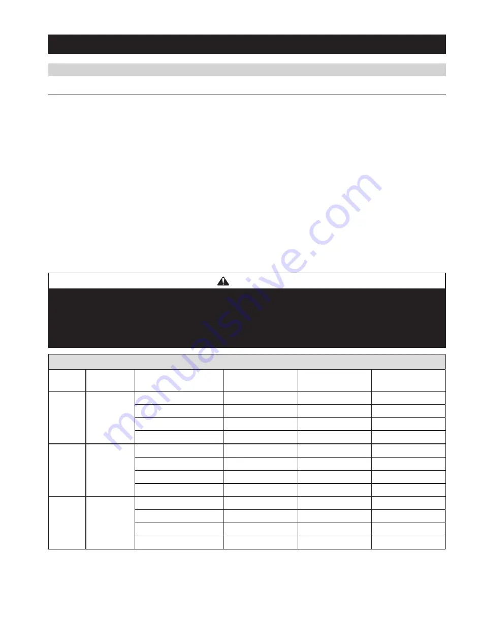
Table 2
provides absorption distance for typical conditions .
The higher the RH setting, the longer the absorption distance . Warmer air shortens the absorption distance . If absorption distance is a concern,
install dispersion tube in supply duct and configure humidifier and control to operate only during HVAC system heat call . When installing the
humidifier in a system with variable speed blower, determine absorption distance based on airflow at the lowest speed .
The dispersion tube must be mounted with the plate on a vertical surface with the tube angled up as shown in
figure 3
. The steam outlets must
face up regardless of the airflow direction in the duct . The plate is labeled “UP” to indicate proper orientation .
If the dispersion tube is mounted on insulated ductwork, make sure insulation is not more than 2” thick at tube location to prevent insulation
from blocking first steam outlet .
note:
If two dispersion tubes are installed in one duct, double the dispersion distances . If three dispersion tubes are installed, triple the
dispersion distance . Position dispersion tubes so one does not discharge directly onto another .
*Velocity in feet per minute = Duct airflow volume in cubic feet per minute / duct area in square feet .
Example: 1,200 cfm through 16” x 12” duct = 1,200/(12 x 16/144 sq . in ./sq ft .) = 1,200/1 .333 = 900 fpm
InSTallaTIon InSTRUCTIonS
Table 2 – absorption Distance (Minimum distance from dispersion tube downstream to any obstruction or bend in duct)
Input
Power
Humidifier
output
airflow Velocity*
70°f & 30% RH
Setpoint
70°f & 45% RH
Setpoint
65°f & 45% RH
Setpoint
120 V
11 .5 gal/day
300 fpm
7"
11"
13"
600 fpm
3"
6"
7"
1200 fpm
2"
3"
3"
1800 fpm
< 2"
2"
2"
208 V
20 .5 gal/day
300 fpm
13"
19"
23"
600 fpm
6"
10"
12"
1200 fpm
3"
5"
6"
1800 fpm
2"
3"
4"
240 V
23 .3 gal/day
300 fpm
15"
23"
28"
600 fpm
6"
12"
13"
1200 fpm
5"
6"
7"
1800 fpm
3"
4"
5"
CaUTIon
Each humidifier requires its own steam hose and dispersion tube. Do not connect steam hoses from more than one humidifier
together. Back-pressure from one humidifier can lower the water level in the canister in the other humidifier and cause
operational problems.
Do not install the dispersion tube in a duct with greater than 2 in. wg static pressure. High duct pressure can cause back-
pressure in the canister which can result in unstable unit operation.
5


