


INSTALLATION
MANUAL 50 Hz
CAUTION:
READ ALL SAFETY GUIDES BEFORE YOU
BEGIN TO INSTALL YOUR UNIT.
SAVE THIS MANUAL
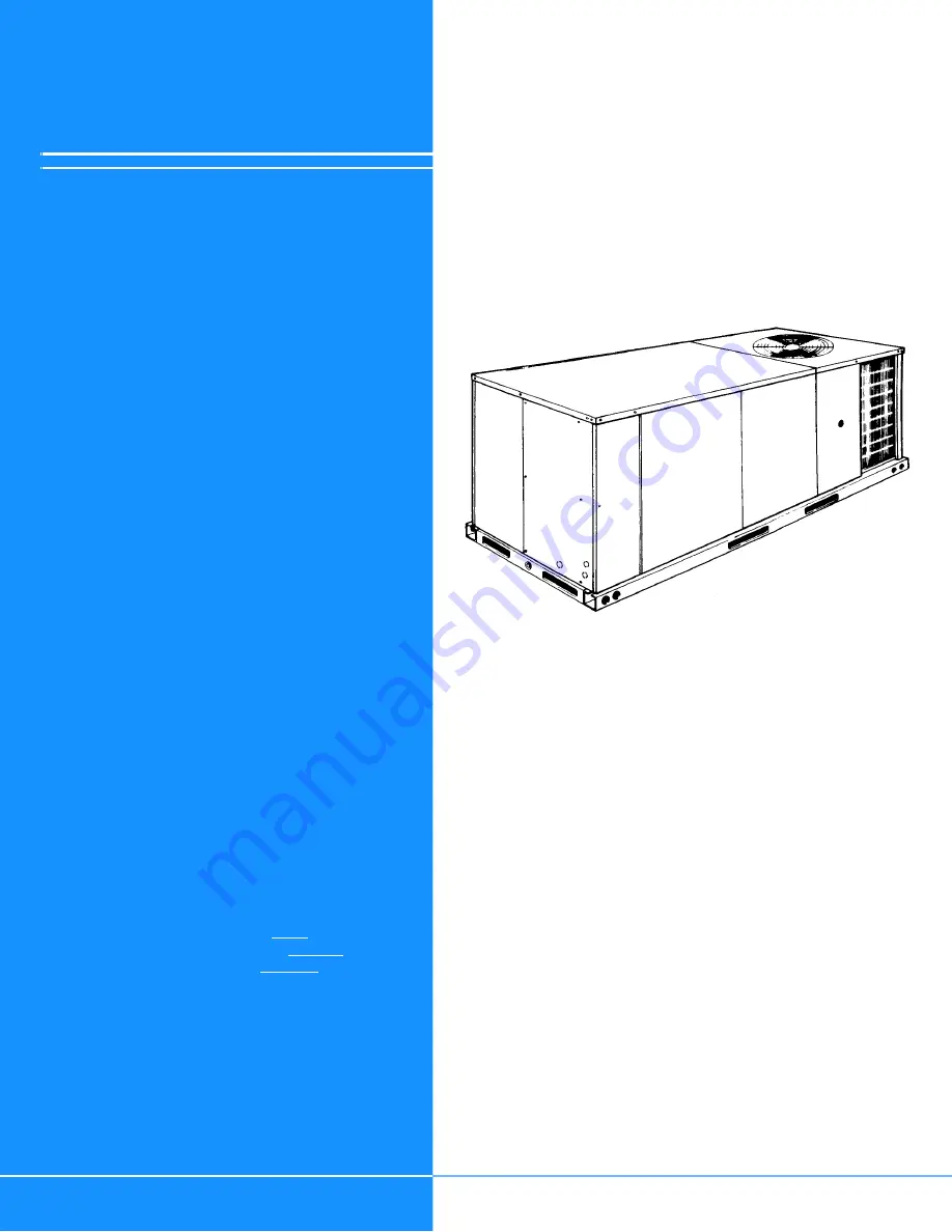
SUNLINE 2000™
SINGLE PACKAGE HEAT PUMP
BQ 036, 048 & 060
(EXPORT)
175619-XIM-C-0109
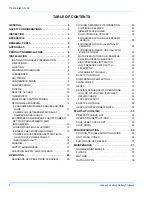
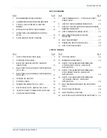
CONTENTS
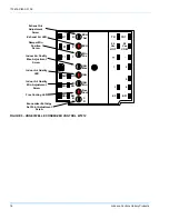
UNIT CONTROL BOARD FLASH CODES
37GENERAL . . . . . . . . . . . . . . . . . . . . . . . . . . . . . . 4
SAFETY CONSIDERATIONS . . . . . . . . . . . . . . . . . 4
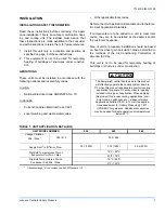
INSPECTION. . . . . . . . . . . . . . . . . . . . . . . . . . . . . . 4
REFERENCE. . . . . . . . . . . . . . . . . . . . . . . . . . . . . . 4
RENEWAL PARTS . . . . . . . . . . . . . . . . . . . . . . . . . 5
APPROVALS . . . . . . . . . . . . . . . . . . . . . . . . . . . . . 5
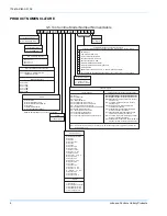
PRODUCT NOMENCLATURE . . . . . . . . . . . . . . . . 6
INSTALLATION . . . . . . . . . . . . . . . . . . . . . . . . . . . 7
OPERATION . . . . . . . . . . . . . . . . . . . . . . . . . . . . . 29
START-UP (COOLING) . . . . . . . . . . . . . . . . . . . . 33
TROUBLESHOOTING . . . . . . . . . . . . . . . . . . . . . 33
MAINTENANCE . . . . . . . . . . . . . . . . . . . . . . . . . . 37
See the following page for a complete Table of Con-
tents.
NOTES, CAUTIONS AND WARNINGS
Installer should pay particular attention to the words:
NOTE
,
CAUTION
, and
WARNING
. Notes are intended to
clarify or make the installation easier. Cautions are given
to prevent equipment damage. Warnings are given to
alert installer that personal injury and/or equipment dam-
age may result if installation procedure is not handled
properly.


