


341426-BIM-A-0108
Johnson Controls Unitary Products
5
CLEARANCES
All units require certain clearances for proper operation and
service. Refer to Table 10 for the clearances required for
combustion, construction, servicing and proper unit opera-
tion.
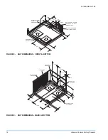
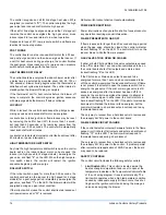
DUCT WORK
These units are adaptable to downflow use as well as rear
supply and return air duct openings. To convert to downflow,
use the following steps:
1.
Remove the duct covers found in the bottom return and
supply air duct openings. There are four (4) screws
securing each duct cover (save these screws to use
later).
2.
Install the duct covers, removed in step one, to the rear
supply and return air duct openings. Secure with the four
(4) screws used in step one.
3.
Seal duct covers with silicone caulk.
Duct work should be designed and sized according to the
methods of the Air Conditioning Contractors of America
(ACCA), as set forth in their Manual D.
A closed return duct system shall be used. This shall not pre-
clude use of economizers or ventilation air intake. Flexible
joints may be used in the supply and return duct work to min-
imize the transmission of noise.
NOTE:
Be sure to note supply and return openings.
Refer to Figure 9 for information concerning rear and bottom
supply and return air duct openings.
ROOF CURB
On applications when a roof curb is used, the unit must be
positioned on the curb so the front of the unit is tight against
the curb.
FILTERS
A filter rack and a high velocity filters are standard.
Filters must always be used and must be kept clean. When
filters become dirt laden, insufficient air will be delivered by
the blower, decreasing your units efficiency and increasing
operating costs and wear-and-tear on the unit and controls.
Filters should be checked monthly especially since this unit is
used for both heating and cooling.
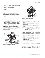
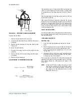
CONDENSATE DRAIN
A condensate trap is recommended to be installed in the con-
densate drain. The plumbing must conform to local codes.
Use a sealing compound on male pipe threads. Install the
condensate drain line (NPTF) to spill into an open drain.
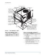
SERVICE ACCESS
Access to all serviceable components is provided by the fol-
lowing removable panels:
•
Blower compartment
•
Gas control/electrical service access
Refer to Figure 7 for location of these access panels and min-
imum clearances.
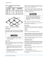
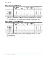
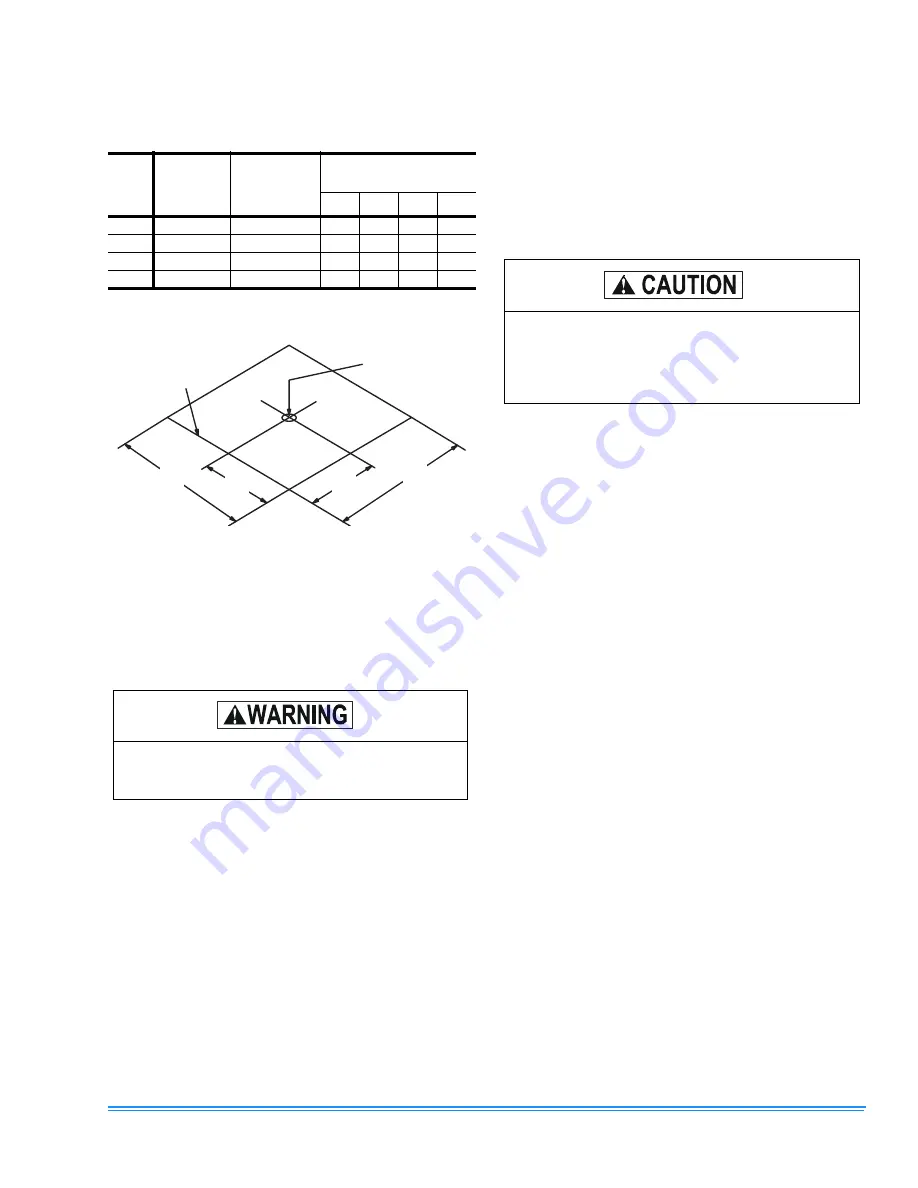
TABLE 2: UNIT WEIGHTS AND CENTER OF
GRAVITY
UNIT
SIZE
SHIPPING
WEIGHT
(LBS.)
OPERATING
WEIGHT
(LBS.)
CORNER WEIGHTS
(LOCATION, LBS.)
“A”
“B”
“C”
“D”
036
400
395
100
96
98
101
042
410
405
104
100
101
105
048
475
470
119
115
116
120
060
480
475
120
116
117
122
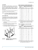
FIGURE 2 - UNIT CENTER OF GRAVITY
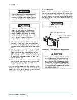
Do not permit overhanging structures or shrubs to
obstruct the condenser air discharge, combustion
air inlet or vent outlet.
"A"
"B"
"C"
"D"
49-1/8
25
25
47-1/4
FRONT
OF
UNIT
CENTER OF
GRAVITY
When fastening duct work to the side duct flanges
on the unit, insert the screws through the duct
flanges only. Do not insert the screws through the
casing. Outdoor ductwork must be insulated and
waterproofed.


