background image

341426-BIM-A-0108

8

Johnson Controls Unitary Products

GAS PIPING

Proper sizing of gas piping depends on the cubic feet per
hour of gas flow required, specific gravity of the gas and the
length of run. National Fuel Gas Code Z223.1 or CAN/CGA
B149.1 or .2 should be followed in all cases unless super-
seded by local codes or gas company requirements. Refer to
Tables 5 and 6.

The heating value of the gas may differ with locality. The
value should be checked with the local gas utility.

NOTE:

There may be a local gas utility requirement specify-
ing a minimum diameter for gas piping. All units
require a 1/2 inch pipe connection at the gas valve.
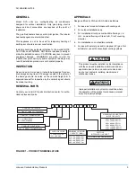
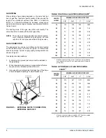
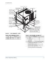
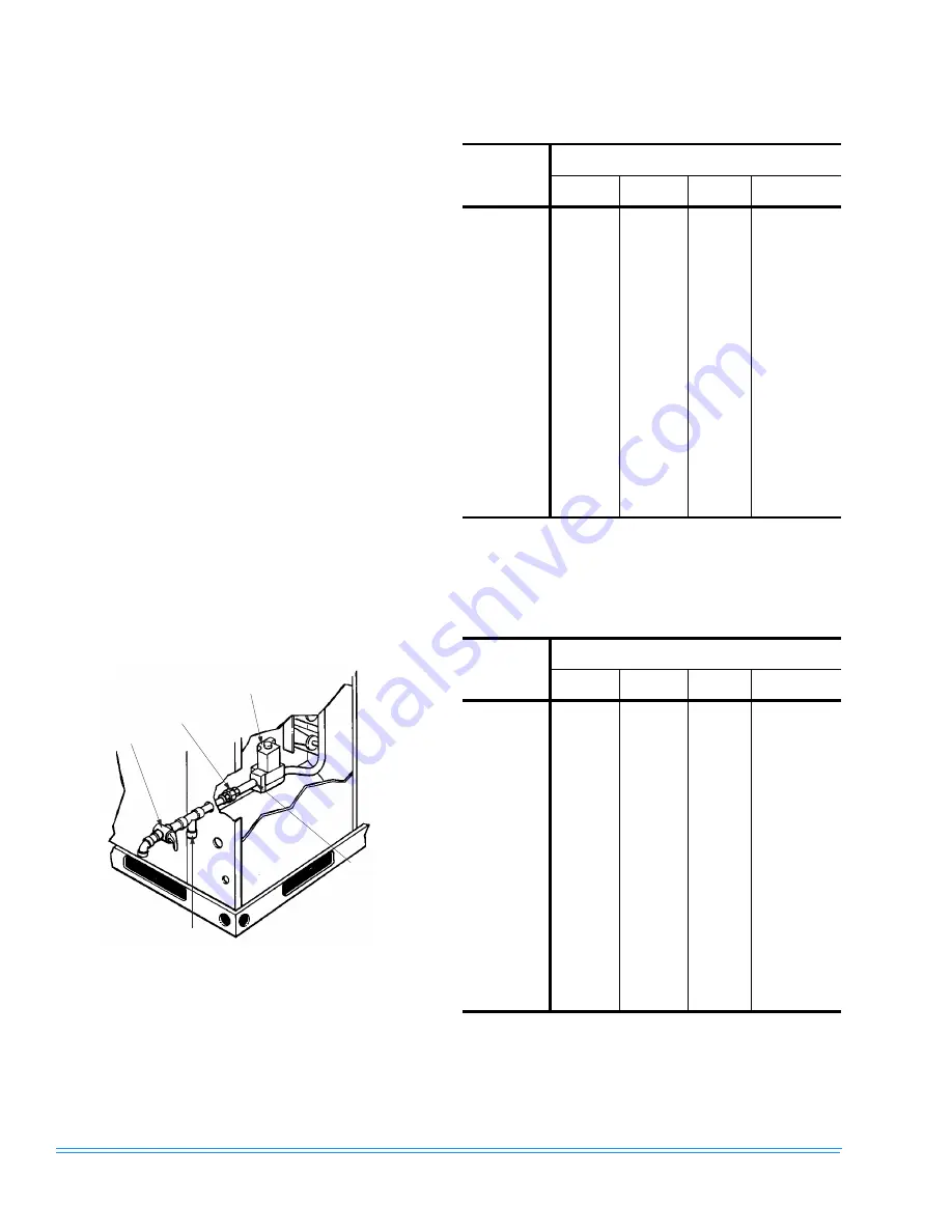
GAS CONNECTION

The gas supply line can be routed through the hole located
on the left side of the unit. Refer to Figure 7 to locate these
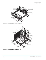
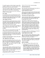
access openings. Typical supply piping arrangements are
shown in Figure 5.

Gas piping recommendations:
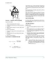
1.

A drip leg and a ground joint union must be installed in 
the gas piping.

2.

When required by local codes, a manual shut-off valve 
may have to be installed outside of the unit.

3.

Use wrought iron or steel pipe for all gas lines. Pipe dope 
should be applied sparingly to male threads only.

.

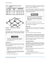
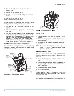
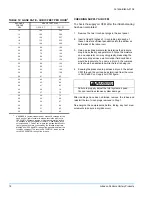
FIGURE 5 -  EXTERNAL SUPPLY CONNECTION 

EXTERNAL SHUT-OFF

1 / 2   x   1 / 2   G A S   C O C K

1 / 2   x   1 / 2   U N I O N

A U T O M A T I C

G A S   V A L V E

D R I P   L E G

1 / 2   -   1 4 N P T

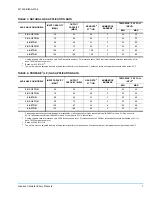
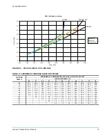
TABLE 5: NATURAL GAS PIPE SIZING CHART

1

1.

Maximum capacity of pipe in cubic feet of gas per hour (based 
upon a pressure drop of 0.3 inch water column and 0.6 specific 
gravity gas).

LENGTH

IN FEET

NOMINAL INCHES IRON PIPE SIZE

1/2”

3/4”

1”

1-1/4”

10

132

278

520

1,050

20

92

190

350

730

30

73

152

285

590

40

63

130

245

500

50

56

115

215

440

60

50

105

195

400

70

46

96

180

370

80

43

90

170

350

90

40

84

160

320

100

38

79

150

305

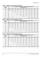
TABLE 6: PROPANE (LP) GAS PIPE SIZING 

CHART

1

1.

Maximum capacity of pipe in thousands of BTU per hour (based 
upon a pressure drop of 0.5 inch water column).

LENGTH

IN FEET

NOMINAL INCHES IRON PIPE SIZE

1/2”

3/4”

1”

1-1/4”

10

275

567

1,071

2,205

20

189

393

732

1,496

30

152

315

590

1,212

40

129

267

504

1,039

50

114

237

448

913

60

103

217

409

834

70

96

196

378

771

80

89

185

346

724

90

83

173

322

677

100

78

162

307

630

Summary of Contents for 341426-BIM-A-0108

Page 1: ...s are intended to clarify or make the installation easier Cautions are given to prevent equipment damage Warnings are given to alert installer that personal injury and or equipment damage may result if installation procedure is not handled properly CAUTION READ ALL SAFETY GUIDES BEFORE YOU BEGIN TO INSTALL YOUR UNIT INSTALLATION MANUAL SAVE THIS MANUAL SINGLE PACKAGED GAS ELECTRIC AIR COOLED AIR C...

Page 2: ...RAL GAS 17 CHECKING SUPPLY AIR CFM 18 TYPICAL WIRING DIAGRAM NOTES 23 LIST OF FIGURES Fig Pg 1 PRODUCT NOMENCLATURE 3 2 UNIT CENTER OF GRAVITY 5 3 TYPICAL FIELD CONTROL WIRING DIAGRAM 6 4 TYPICAL FIELD POWER WIRING DIAGRAM 6 5 EXTERNAL SUPPLY CONNECTION EXTERNAL SHUT OFF 8 6 FLUE VENT OUTLET AIR HOOD 9 7 UNIT DIMENSIONS FRONT 11 8 UNIT DIMENSIONS FRONT BOTTOM 12 9 UNIT DIMENSIONS BACK BOTTOM 12 10...

Page 3: ...nter for autho rized replacement parts APPROVALS Design certified by CGA and AGA listed as follows 1 For use as a forced air furnace with cooling unit 2 For outdoor installation only 3 For installation directly on combustible flooring or in U S on wood flooring or Class A B C roof covering material 4 For installation on combustible material 5 For use with natural gas and or propane LP gas Not suit...

Page 4: ...ron frame providing adequate support under the compressor condenser section 5 Maintain level tolerance of unit to 1 8 maximum RIGGING OR HANDLING Care must be exercised when moving the unit Do not remove any packaging until the unit is near the place of installation Rig unit with slings placed under the unit Spreader bars of sufficient length should be used across the top of the unit Units may als...

Page 5: ...is tight against the curb FILTERS A filter rack and a high velocity filters are standard Filters must always be used and must be kept clean When filters become dirt laden insufficient air will be delivered by the blower decreasing your units efficiency and increasing operating costs and wear and tear on the unit and controls Filters should be checked monthly especially since this unit is used for ...

Page 6: ...th mechanical strain relief A fused disconnect switch should be field provided for the unit If any of the wire supplied with the unit must be replaced replacement wire must be of the type shown on the wiring diagram Electrical line must be sized properly to carry the load Each unit must be wired with a separate branch circuit fed directly from the meter panel and properly fused Refer to Figure 4 f...

Page 7: ... below 55 F TABLE 4 PROPANE1 LP GAS APPLICATION DATA AVAILABLE ON MODELS INPUT CAPACITY MBH 2 OUTPUT CAPACITY MBH GAS RATE3 FT 3 HR NUMBER OF BURNERS TEMP RISE F AT FULL INPUT4 MIN MAX 3 3 1 2 TON 45 36 18 2 25 55 3 3 1 2 TON 70 56 28 3 25 55 4 5 TON 80 64 32 3 25 55 3 3 1 2 TON 90 72 36 4 30 60 4 5 TON 108 87 43 4 30 60 4 5 TON 135 108 54 5 35 65 1 Propane applications are accomplished by field i...

Page 8: ...l codes a manual shut off valve may have to be installed outside of the unit 3 Use wrought iron or steel pipe for all gas lines Pipe dope should be applied sparingly to male threads only FIGURE 5 EXTERNAL SUPPLY CONNECTION EXTERNAL SHUT OFF 1 2 x 1 2 G A S C O C K 1 2 x 1 2 U N I O N A U T O M A T I C G A S V A L V E D R I P L E G 1 2 1 4 N P T TABLE 5 NATURAL GAS PIPE SIZING CHART1 1 Maximum capa...

Page 9: ...d attached This hood must be installed to assure proper unit operation The hood must be fastened to the outside of the side gas control electrical compartment with the screws provided in the bag attached to the inside of the gas control electrical compart ment see Figure 6 If flexible stainless steel tubing is allowed by the authority having jurisdiction wrought iron or steel pipe must be installe...

Page 10: ...SOR TYPE HERMETICALLY SEALED R RECIPROCATING S SCROLL R R S S 1 Three phase 036 thru 042 size units are supplied with one 1 filter and on three phase 048 and 060 size units two 2 filters are supplied See FILTERS on page 5 TABLE 8 ELECTRICAL DATA MODEL DYA POWER SUPPLY VOLTAGE LIMITATIONS1 COMPRESSOR COND FAN MOTOR FLA SUPPLY AIR BLOWER MOTOR FLA MINIMUM CIRCUIT AMPACITY MAX FUSE SIZE AMPS2 MAX HAC...

Page 11: ...N A I R I N L E T L O U V E R S F R O N T G A S E L E C T R I C C O N T R O L S E R V I C E A C C E S S C O M P A R T M E N T P A N E L O V E R A L L O V E R A L L All dimensions are in inches They are subject to change with out notice Certified dimensions will be provided upon request TABLE 9 UNIT DIMENSIONS FRONT UNIT SIZE DIMENSION A B 036 and 042 33 1 2 18 1 4 048 and 060 41 1 2 23 1 8 TABLE 1...

Page 12: ... P P L Y 1 5 8 D I A K N O C K O U T 1 2 N P T I C O N N E C T I O N L O W V O L T A G E C O N N 1 8 D I A K N O C K O U T FIGURE 9 UNIT DIMENSIONS BACK BOTTOM 1 3 4 1 5 2 9 9 1 6 1 5 3 1 2 1 3 4 1 3 4 1 5 4 1 4 1 2 3 1 2 3 3 8 1 4 1 2 2 8 3 8 1 4 1 2 C O N D E N S E R C O I L B O T T O M S U P P L Y A I R O P E N I N G B O T T O M R E T U R N A I R O P E N I N G S I D E R E T U R N A I R O P E N ...

Page 13: ...rge period before de energizing If the pressure switch is lost during an ignition trial period the control immediately de energizes spark and gas The control begins pressure switch proving before an inter purge and re ignition attempt PILOT FLAME STABILIZATION PERIOD The control board de energizes the spark output and waits for a 2 second flame stabilization period before energizing the main gas v...

Page 14: ...t will be energized during an open rollout condition If the rollout switch closes the control shall remain locked out until power removed or W is removed Rollout switch lockout shall not reset automatically POWER INTERRUPTIONS Power interruptions of any duration shall not cause lockout or any operation requiring manual intervention FLAME PRESENT WITH GAS OFF If flame is sensed for longer than 4 0 ...

Page 15: ...all for HEAT occurs the circulating fan switches to heat speed after a 30 second delay When the thermostat ends the call for FAN the thermostat terminal G is de energized de energizing the circulating fan START UP PRE START CHECK LIST Complete the following checks before starting the unit 1 Check the type of gas being supplied Be sure that it is the same as listed on the unit nameplate 2 Make sure...

Page 16: ...ting screw on the automatic gas valve Refer to Figure 10 Adjust as follows 1 Remove the cap from the valve body See Figure 10 for location 2 To decrease the gas pressure turn the adjusting screw counterclockwise 3 To increase the gas pressure turn the adjusting screw clockwise NOTE The correct manifold pressure for natural gas fur naces is 3 5 IWG The correct manifold pressure for propane LP is 10...

Page 17: ...rature rise decrease the blower CFM to increase the rise DIRECT DRIVE BLOWER All units have direct drive multi speed blower motors Refer to the unit wiring diagram and connect the blower motor for the desired motor speed CHECKING GAS INPUT NATURAL GAS 1 Turn off all other gas appliances connected to the gas meter 2 With the furnace turned on measure the time needed for one revolution of the hand o...

Page 18: ... inch plugs removed in Step 1 De energize the compressors before taking any test mea surements to ensure a dry indoor coil TABLE 12 GASE RATE CUBIC FEET PER HOUR1 1 EXAMPLE By actual measurement it takes 38 seconds for the hand on the 1 cubic foot dial to make a revolution with just a 100 000 BTUH furnace running Using this information locate 38 seconds in the first column of Table 12 Read across ...

Page 19: ...F 55 57 59 61 63 65 67 69 71 73 75 65 27 1 28 4 29 7 31 1 32 4 33 7 35 0 35 9 36 8 37 6 38 5 70 23 3 24 8 26 2 27 7 29 2 30 6 32 1 33 5 34 9 36 4 37 8 75 19 5 21 1 22 7 24 4 26 0 27 6 29 2 31 2 33 1 35 1 37 1 80 15 7 17 5 19 2 21 0 22 8 24 5 26 3 28 8 31 3 33 8 36 3 85 11 9 13 8 15 7 17 6 19 6 21 5 23 4 26 5 29 5 32 6 35 6 90 8 6 10 6 12 6 14 6 16 6 18 6 20 6 24 1 27 6 31 1 34 6 95 5 3 7 4 9 5 11 ...

Page 20: ...6 18 7 19 7 20 7 21 7 22 7 23 7 25 2 26 6 28 1 29 6 75 14 4 15 5 16 6 17 8 18 9 20 0 21 2 22 9 24 7 26 4 28 2 80 11 1 12 4 13 6 14 9 16 1 17 4 18 6 20 7 22 7 24 8 26 8 85 7 8 9 2 10 6 12 0 13 3 14 7 16 1 18 4 20 8 23 1 25 4 90 5 8 7 0 8 2 9 3 10 5 11 7 12 9 15 7 18 6 21 5 24 4 95 5 8 6 7 7 7 8 6 9 6 13 0 16 5 19 9 23 3 100 5 4 6 0 6 7 7 4 8 0 11 6 15 2 18 7 22 3 105 5 3 5 7 6 1 6 5 10 2 13 9 17 6 ...

Page 21: ...341426 BIM A 0108 Johnson Controls Unitary Products 21 FIGURE 14 TYPICAL WIRING DIAGRAM DYA 036 042 048 060 208 230 3 60 POWER SUPPLY ...

Page 22: ...341426 BIM A 0108 22 Johnson Controls Unitary Products FIGURE 15 TYPICAL WIRING DIAGRAM DYA 036 042 048 060 460 3 60 POWER SUPPLY ...

Page 23: ...ent wire 801 BL and 805 BL are connected to ASCT 3 If only LR is present wire 801 BL and 805 BL are connected to M1 coil If only ASCT is present wire 202 Y is connected to ASCT 3 If neither LR or ASCT are present wire 202 Y is connected to M1 coil as shown 7 Shunt contact also used with crankcase heater optional 8 Unit factory wired for low or medium speed indoor blower operation To change motor s...

Page 24: ...R OPTIONAL BR BLOWER RELAY CB CIRCUIT BREAKER CCH CRANK CASE HEATER OPTIONAL COMPR COMPRESSOR DM DRAFT MOTOR FCB FAN CONTROL BOARD GND GROUND FS FREEZE STAT SWITCH OPTIONAL HP HIGH PRESSURE SWITCH OPENS 380 PSIG IDFAN INDOOR FAN MOTOR LP LOW PRESSURE SWITCH OPENS 7 PSIG LS LIMIT SWITCH LR LOCK OUT RELAY OPTIONAL M1 CONTACTOR COMPR AND OD FAN ODFAN OUTDOOR FAN MOTOR PS PRESSURE SWITCH RC1 RC2 COMPR...

Reviews: