


341426-BIM-A-0108
Johnson Controls Unitary Products
9
i
4.
All piping should be cleaned of dirt and scale by ham-
mering on the outside of the pipe and blowing out the
loose dirt and scale. Before initial start-up, be sure that
all of the gas lines external to the unit have been purged
of air.
5.
The gas supply should be a separate line and installed in
accordance with all safety codes as prescribed under
Limitations. After the gas connections have been com-
pleted, open the main shut-off valve admitting normal
gas pressure to the mains. Check all joints for leaks with
soap solution or other material suitable for the purpose.
NEVER USE A FLAME.
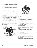
6.
The furnace and its individual manual shut-off valve must
be disconnected from the gas supply piping system dur-
ing any pressure testing of that system at test pressures
in excess of 1/2 psig (3.48 kPa).
The furnace must be isolated from the gas supply piping sys-
tem by closing its individual manual shut-off valve during any
pressure testing of the gas supply piping system at test pres-
sures equal to or less than 1/2 psig (3.48 kPa).
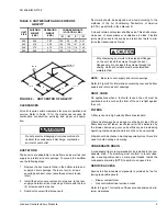
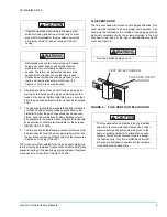
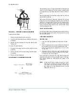
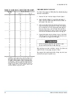
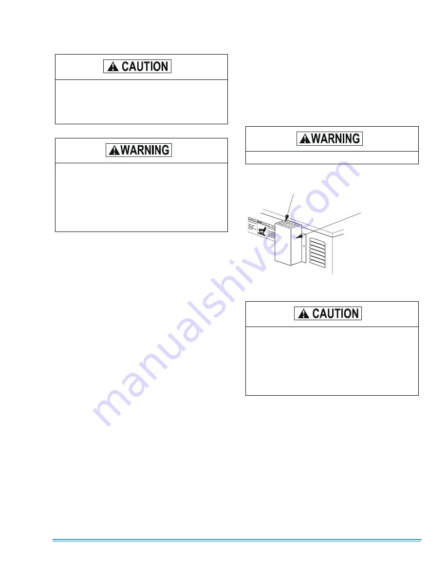
FLUE VENT HOOD
The flue vent hood with screen is not shipped attached. This
hood must be installed to assure proper unit operation. The
hood must be fastened to the outside of the side gas control/
electrical compartment with the screws provided in the bag
attached to the inside of the gas control/electrical compart-
ment, see Figure 6.
If flexible stainless steel tubing is allowed by the
authority having jurisdiction, wrought iron or steel
pipe must be installed at the gas valve and extend
a minimum of two (2) inches outside of the unit
casing.
Natural gas may contain some propane. Propane
being a excellent solvent, will quickly dissolve
white lead or most standard commercial com-
pounds. Therefore, a special pipe dope must be
applied when wrought iron or steel pipe is used.
Shellac base compounds such as gaskoloc or sta-
lastic, and compounds such as rectorseal # 5,
Clyde’s or John Crane may be used.
Flue hood surfaces may be hot.
FIGURE 6 - FLUE VENT OUTLET AIR HOOD
The flue exhaust hood must be properly installed
and within the recommended clearances. Further
communications and action must be given to the
home or building owner(s) to eliminate any unau-
thorized human contact around this area during
the heating cycle. Flue hood surface and immedi-
ate area are designed to operate at high tempera-
tures during the heating cycle.
V E N T O U T L E T S C R E E N
F L U E V E N T O U T L E T
A I R H O O D


