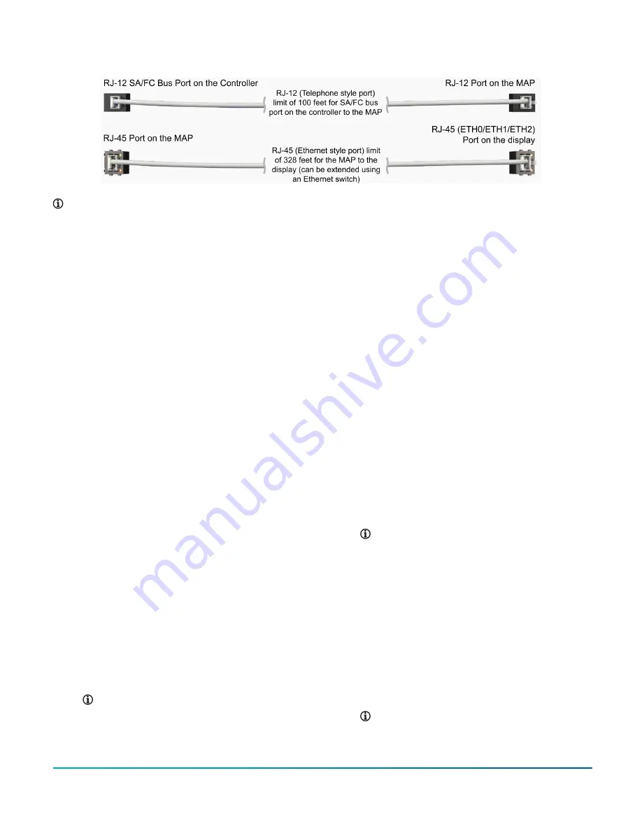
Figure 7: MAP and display connection: RJ-12 and RJ-45
Note:
1. Field to provide cable length as required.
2. When using an Ethernet switch, the MAP must be powered using an external power source. Refer
to Figure 12 for an example of the Ethernet switch.
Procedure overview
Install the display
Mount display on a wall or in a remote
panel
1.
a. When mounting the display on a wall,
attach the wall-mounting box to the
wall, and place the display onto the
box.
b. When mounting the display in a
remote panel, insert the display into
the existing cutout in the control
panel.
2. Connect the serial communications cable,
MAP cable, and power supply to the display.
3. Connect the serial communications and MAP
cables from the display to the controller, and
apply power to the display.
Cable the display to the unit
To establish a direct connection to the controller:
1. Connect the serial communications cable into
the communication port labeled SERIAL on
the display unit. Plug the other end of the
serial communications cable into the SA bus
adapter on the controller.
2. Connect the Ethernet cable from the MAP to
the port labeled ETH2 on the display using
a RJ-45 style cable. Use a RJ-12 style cable to
connect the MAP with the SA bus modular jack
provided on the controller.
Note:
for instructions to set up
the MAP.
3. Connect a 24 VDC supply voltage to power up
the display.
To extend the serial communications cable in order
to view field bus devices:
1. The display can integrate multiple field
bus devices on Metasys
®
systems, Facility
Explorer
®
systems, Smart Equipment rooftop
units (RTUs) with unit control boards (UCBs),
Johnson Controls
®
branded field controllers,
including FEC, FAC, VMA, PCA, PCG, PCV Series
devices, TEC3000 Series thermostats, and
other Applied Smart Equipment controllers
using the MAP.
2. Connect the serial communications cable
into the communication port labeled SERIAL
on the display unit. Plug the other end of
the serial communications cable into the FC
bus adapter of the controller. Multiple field
devices can be connected on the FC bus of the
controller that are on a common MS/TP bus.
Note:
In the
section
3. Connect the Ethernet cable from the MAP
to any of the Ethernet ports (ETH0/ETH1/
ETH2). This guide shows the RJ-45 style cable
connected to the ETH2 port on the display.
Use a RJ-12 style cable to connect the MAP
with the FC bus modular jack provided on the
controller. Order Option 1 for touchscreen
display installation when the unit is with a
factory installed MAP. Order Option 2 for
touchscreen display installation when the unit
is without a factory installed MAP.
Note:
the MAP.
Advanced Graphic Touchscreen Display on 25 Ton to 80 Ton Johnson Controls Premier Rooftop Units
11
Johnson Controls


