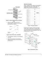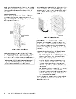
BD-1300 Control Dampers Installation Instructions
4
Note:
All dampers between 48 and 96 inches in width
will be factory coupled pin-to-pin only unless jackshaft
(Factory Option J in the
Damper Selection Tool
) is
requested.
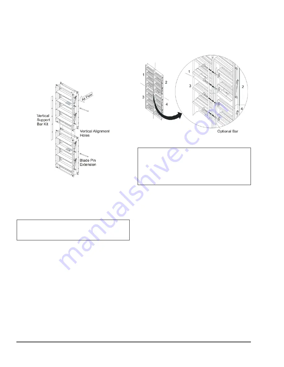
Vertical Coupling
If the vertically coupled damper sections both operate
normally open or normally closed, connect them
together vertically with both linkage ends on the same
side as shown in Figure 9.
Attach the coupling hardware on the linkage side of
one damper section to the same odd numbered blade
of the other damper section. The vertical alignment
holes can be used to couple vertical dampers together.
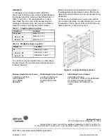
Vertical reinforcement requirements vary based on the
size and number of damper sections forming the unit
and the closed off static pressure. Build reinforcements
from the DMPR-KC200 Support Bar Kit as shown in
Figure 10.
The following recommendations are based on tests
with 24 x 24 inch and 48 x 48 inch sections:
•
Dampers having less than four blades per damper
utilize one support bar. Four or more blades per
damper utilize two support bars.
•
Up to four dampers with a combined area up to
16 square feet maximum, based on a closed off
static pressure up to 4 inch water gauge (WG),
utilize one support bar; 4 to 8 inch WG utilize two
support bars.
•
Dampers with a combined area of 14 to 64 square
feet maximum, based on a closed off static
pressure up to 2 inch WG, utilize two support bars;
2 to 4 inch WG utilize four support bars; and above
4 inch WG consult the factory.
For more information on kits to couple damper blades,
refer to
M9000 Damper Accessory Kits Technical
Bulletin (LIT-2681105
).
IMPORTANT:
Do not insert screws in the vertical
alignment holes in the top and bottom channels
where they will interfere with blade operation.
Figure 9: Vertical Coupling
IMPORTANT:
All installations which combine
vertically and horizontally joined sections must be
reinforced at the point where the four sections meet.
The amount and type of reinforcement is based on
the actual mounting arrangements, applications, and
functions.
Figure 10: Support Bar Kit


