Published in U.S.A.
www.johnsoncontrols.com
BD-1300 Control Dampers Installation Instructions
5
Metasys® and Johnson Controls® are registered trademarks of Johnson Controls, Inc.
All other marks herein are the marks of their respective owners. © 2016 Johnson Controls, Inc.
Building Efficiency
507 E. Michigan Street, Milwaukee, WI 53202
Actuators
For dampers using a single actuator, install the
direct-mount actuator or associated actuator linkage to
the linkage side of the preferred drive blade shown in
Table 1 and Table 2. The ideal situation is to use a
drive blade near the center of the damper height to
distribute the torque evenly. Use only odd numbered
blades for dampers with opposed blade rotation.
The actuators may be installed frame mounted inside
the duct (Figure 10) or wall mounted outside the duct at
locations indicated.
Attach one actuator to the preferred driving blade on
the linkage side of each damper section. Refer to the
appropriate actuator literature for proper damper sizing
information.
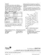
For frame mount actuator drives, when two sections
are coupled horizontally, the ideal situation is to mount
the actuator in the air stream at the junction of the two
damper sections as shown in Figure 11.
Table 1: Single Actuator Location
Height, in.
Location
24 or less
Blade No. 1 or 3
24 but
48
Blade No. 3 or 5
48 but
76
Blade No. 5 or 7
Table 2: Multiple Actuator Location
Height, in.
Location
30
Blade Nos. 3 and 5
30 but
48
Blade Nos. 3 and 7
48 but
76
Blade Nos. 3 and 9
Figure 11: Actuator Bracket Location
European Single Point of Contact:
NA/SA Single Point of Contact:
APAC Single Point of Contact:
JOHNSON CONTROLS
WESTENDHOF 3
45143 ESSEN
GERMANY
JOHNSON CONTROLS
507 E MICHIGAN ST
MILWAUKEE WI 53202
USA
JOHNSON CONTROLS
C/O CONTROLS PRODUCT MANAGEMENT
NO. 22 BLOCK D NEW DISTRICT
WUXI JIANGSU PROVINCE 214142
CHINA


