P5417050-rev.1
25
8. All electrical work should be performed in strict accordance with electrical schematics in the
"Installation and Maintenance Manual".
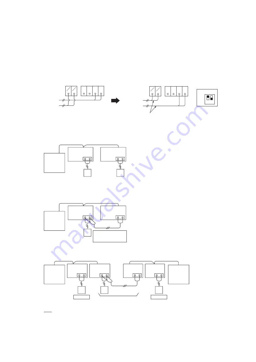
9. If Power Supply Voltage (208V/230V) is introduced into the Communication Line:
If 208V/230V are applied to the communication line at (Terminals 1 and 2 of TB2) by mistake, the fuse
on the PCB for the communication line will blow. In this case, perform the recovery work as shown in
the diagrams below.
a. Reconnect the wirings correctly.
b. Set the No.1 pin at DSW7 (on the PCB) to ON.
After the fuse is replaced and the PCB recovers, do not reintroduce 208V/230V into the communication
line. This voltage causes serious damage to the PCB, and it will not recover.
c. Wired Controller connections between different refrigerant systems
a. Wired Controllers at each unit for an individual operation setting
b. Single Wired Controller for an individual operation setting
Outdoor Unit
A B
Outdoor Unit
Indoor Unit
Indoor Unit
Indoor Unit
Indoor Unit
A B
A B
A B
Individual
Simultaneous
(Thermo ON / OFF individually)
Individual
Wired
Controller
Wired
Controller
Wired
Controller
NOTE:
Thermo-ON: The outdoor unit and some indoor units are running.
Thermo-OFF: The outdoor unit and some indoor units stay on, but don’t run.
Indoor Unit
Indoor Unit
A B
Outdoor Unit
A B
Wired
Controller
Wired
Controller
10. Wired Controller Connections
L1
R
L2
AC 208V/230V
Incorrect Wiring
Reconnect wirings correctly.
5V
A B 1
2
S
L1
R
L2
AC 208V/230V
5V
A B 1
2
S
ON
OFF
DSW7
Set No.1 Pin
at ON side.
PCB
1 2
Outdoor Unit
Indoor Unit
A B
Communication cables
for the wired controller
are necessary.
Indoor Unit
A B
Wired
Controller


