


Table 12: CV series controller accessories (order separately)
Product code number
Description
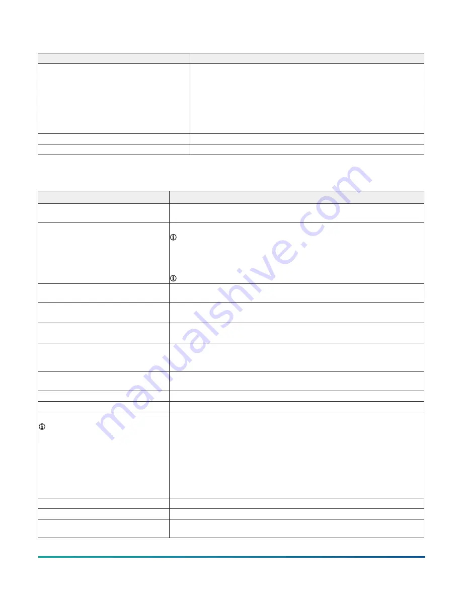
MS-FIT100-0
The Field Inspection Tool (FIT) is a portable handheld device with a user interface
that is used to test and troubleshoot the BACnet protocol MS/TP RS-485
communications bus that connects supervisory controllers and equipment
controllers to field point interfaces.
The FIT can be used to check out the wiring of the MS/TP RS-485 bus as well
as verify proper communications of supervisory controllers and equipment
controllers connected to the bus. The FIT can be used on both the FC Bus and SA
Bus.
TL-BRTRP-0
Portable BACnet/IP to MS/TP Router
M4-CVACT-0R
Actuator Assembly Replacement Kit for use with M4-CV series controllers
Technical specifications
Table 13: CV Series controllers technical specifications
Description
Power Requirement
24 VAC (nominal, 20 VAC minimum/30 VAC maximum), 50/60 Hz, Power Supply Class 2
(North America), Safety Extra-Low Voltage (SELV) (Europe)
Power Consumption
10 VA typical, 14 VA maximum
Note:
The VA rating does not include any power supplied to the peripheral devices
connected to three Outputs (BOs) or Configurable Outputs (COs), which can
consume up to 12 VA for each BO or CO, for a possible total consumption of an
additional 60 VA (maximum). There are 3 BO's and 2 CO's that can each draw 12VA
for a total of 60VA additional power.
Note:
The USB feature is not currently supported.
Power Source
+15 VDC power source terminals provide 35 mA total current. Quantity 1 located in
Universal IN terminals - for active (3-wire) input devices
Ambient Conditions
Operating:
0°C to 50°C (32°F to 122°F) 10% to 90% RH noncondensing
Storage:
-40°C to 70°C (-40°F to 158°F) 5% to 95% RH noncondensing
Network Engines
M4-CVM models:
All network engine model types
M4-CVE03050-0P:
All network engine model types at R9.0 or later
Communications Protocol
M4-CVM models:
BACnet MS/TP; N2. Zigbee Wireless also supported (at FC Bus and for
Sensors) with additional hardware.
M4-CVE03050-0P:
BACnet/IP
Controller Number for Ethernet
Controllers
Set of three rotary switches used to set controller number between 000 and 999. See
Setting the controller number for CVE models
Device Addressing for BACnet MS/TP
Decimal address set via three rotary switches; valid controller device addresses 4-127
Device Addressing for N2
Decimal address set via three rotary switches: valid controller device addresses 1-254
Communications Bus
Note:
For more information, refer to
the
MS/TP Communications Bus Technical
Bulletin (LIT-12011034)
M4-CVM models:
BACnet MS/TP (default), N2
3-wire FC Bus between the supervisory controller and equipment controllers
M4-CVE models:
BACnet/IP
Two Ethernet ports; 10/100 Mbps; 8-pin RJ-45 connector
M4-CVM and M4-CVE models:
4-wire SA Bus between equipment controller, network sensors and other sensor/actuator
devices, includes a lead to source 15 VDC supply power (from equipment controller) to
bus devices
Processor
RX64M 32-bit Renesas microcontroller
Memory
16MB Flash Memory and 8MB SDRAM
Real-Time Clock Backup Power Supply
Super capacitor maintains power to the onboard real-time clock for a minimum of 72
hours when supply power to the controller is disconnected.
M4-CV Series VAV Box Controllers Installation Guide
21


