background image

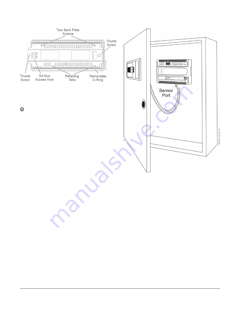
Figure 5: DIS1710 back plate

Wiring

The display receives power over the Sensor-Actuator

(SA) Bus from the NCE, FEC, or FAC controller.

Note: 

 Do not connect the display to an NCE,

FEC, or FAC that has an integral display. Also,

do not connect more than one display on the

same SA Bus.

Connecting cable to controller

Connect the communication cable (included in

box) between the SA Bus connector on the back of

the display and the SA Bus jack on the front of the

controller (Figure 6). The coiled cable is 91 cm (3 ft)

in length and can be stretched to a maximum length

of 152 cm (5 ft).

Figure 6: Connecting the SA bus cable

If the SA Bus jack on the controller is in use, you

can wire the display’s communication cable to

the SA Bus terminal block. Splice one end of the

communication cable and connect it to the SA Bus

terminal block using the wiring designations in

Figure 7.

DIS1710 Local Controller Display Installation Instructions

4

Summary of Contents for DIS1710

Page 1: ...ed and used in accordance with the instruction manual may cause harmful interference to radio communications Operation of this equipment in a residential area may cause harmful interference in which case the users will be required to correct the interference at their own expense Canada This Class A digital apparatus meets all the requirements of the Canadian Interference Causing Equipment Regulati...

Page 2: ...nel Door with Cutout for display Mounting Location considerations The display is mounted onto the front panel door of an enclosure Mounting dimensions and physical features Refer to the following illustrations for the mounting dimensions and physical features of the display Figure 1 DIS1710 Mounting Dimensions mm in Figure 2 DIS1710 physical features Preparing the panel The display is mounted onto...

Page 3: ... 4 Insert the display into the front access hole on the panel door Hold in place 5 Carefully insert the back plate to the other side of the access hole inside of the panel door and secure it to the cutout by hand tightening the two thumbscrews You may need to tilt the back plate to slide it onto the two bottom retaining tabs Figure 4 Attaching the display into panel cutout 6 Using the screwdriver ...

Page 4: ...een the SA Bus connector on the back of the display and the SA Bus jack on the front of the controller Figure 6 The coiled cable is 91 cm 3 ft in length and can be stretched to a maximum length of 152 cm 5 ft Figure 6 Connecting the SA bus cable If the SA Bus jack on the controller is in use you can wire the display s communication cable to the SA Bus terminal block Splice one end of the communica...

Page 5: ...not require commissioning Cable connection between the DIS1710 Local Controller Display and a commissioned field controller allows for immediate display function Ensure that the communication cable is connected between the display and the controller For more information on commissioning refer to the Controller Tool Help LIT 12011147 Troubleshooting Refer to the DIS1710 Local Controller Display Tec...

Page 6: ...CN PAZX UL 916 Energy Management Equipment FCC Compliant to CFR47 Part 15 Subpart B Class A Canada UL Listed File E107041 CCN PAZX7 CAN CSA C22 2 No 205 Signal Equipment Industry Canada Compliant ICES 003 Europe CE Mark Johnson Controls Inc declares that this product is in compliance with the essential requirements and other relevant provisions of the EMC Directive Compliance Australia and New Zea...

Reviews: