288591-BIM-C-0408
Johnson Controls Unitary Products
5
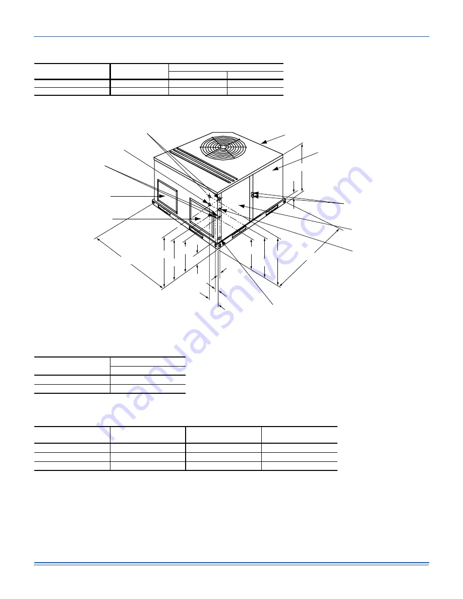
Figure 3:
Unit Dimensions
Note:
For units applied with a roof curb, the minimum clearance may be reduced from 1 inch to 1/2 inch
between combustible roof curb material and this supply air duct.
Table 2:
Unit Accessory Weights
Unit Accessory
Model
Weight (lbs.)
Shipping
Operating
Add Economizer
All
45
40
Add Electric Heat
1
All
13
12
1. Weight given is for the maximum heater size available (25 kW).
FRONT
(OVERALL)
(OVERALL)
(OVERALL)
COMPRESSOR SERVICE
ACCESS COMPARTMENT
PANEL
REFRIGERANT
CONNECTIONS
ELECTRICAL/FILTER
SERVICE ACCESS
COMPARTMENT PANEL
HIGH VOLTAGE CONN.
1-23/64" DIA. KNOCKOUT
UNIT CONDENSATE
CONNECTION 3/4" NPTI
(TRAP REQUIRED)
SIDE RETURN
AIR OPENING
SIDE SUPPLY
AIR OPENING
LOW VOLTAGE CONN.
7/8" DIA. KNOCKOUT
HIGH VOLTAGE CONN.
1-31/32" DIA. KNOCKOUT
HIGH VOLTAGE CONN.
7/8" DIA. KNOCKOUT
“A”
3-3/4
1-1/2
2-1/2
2-1/2
2-3/8
4-1/2
49-1/8
28-1/4
28-1/4
47-1/4
17-1/4
17-1/4
22-1/4
22-1/4
Table 3:
Unit Dimensions Front
Unit Size
Dimensions
“A”
024, 030, 036
33-1/2
042, 048, 060
1
1. DPY Models
41-1/2
Table 4:
Unit Clearances
Direction
Distance
(in.)
Direction
Distance
(in.)
Top
1
1. Units must be installed outdoors. Over hanging structure or shrubs should not obscure condenser air
discharge outlet.
36
Right
24
Front
12
Left
24
Rear
0
Bottom
2
3
2. Units may be installed on combustable floors made from wood or class A, B or C roof covering
materials.
3. Minimum Clearance of 1inch all sides of supply air duct for the first 3 foot of duct for 20 & 25 kW., zero
inches there after. For all other heaters, zero inch clearance all sides for entire length of duct.
0


