background image

2    

F59D Technical Bulletin

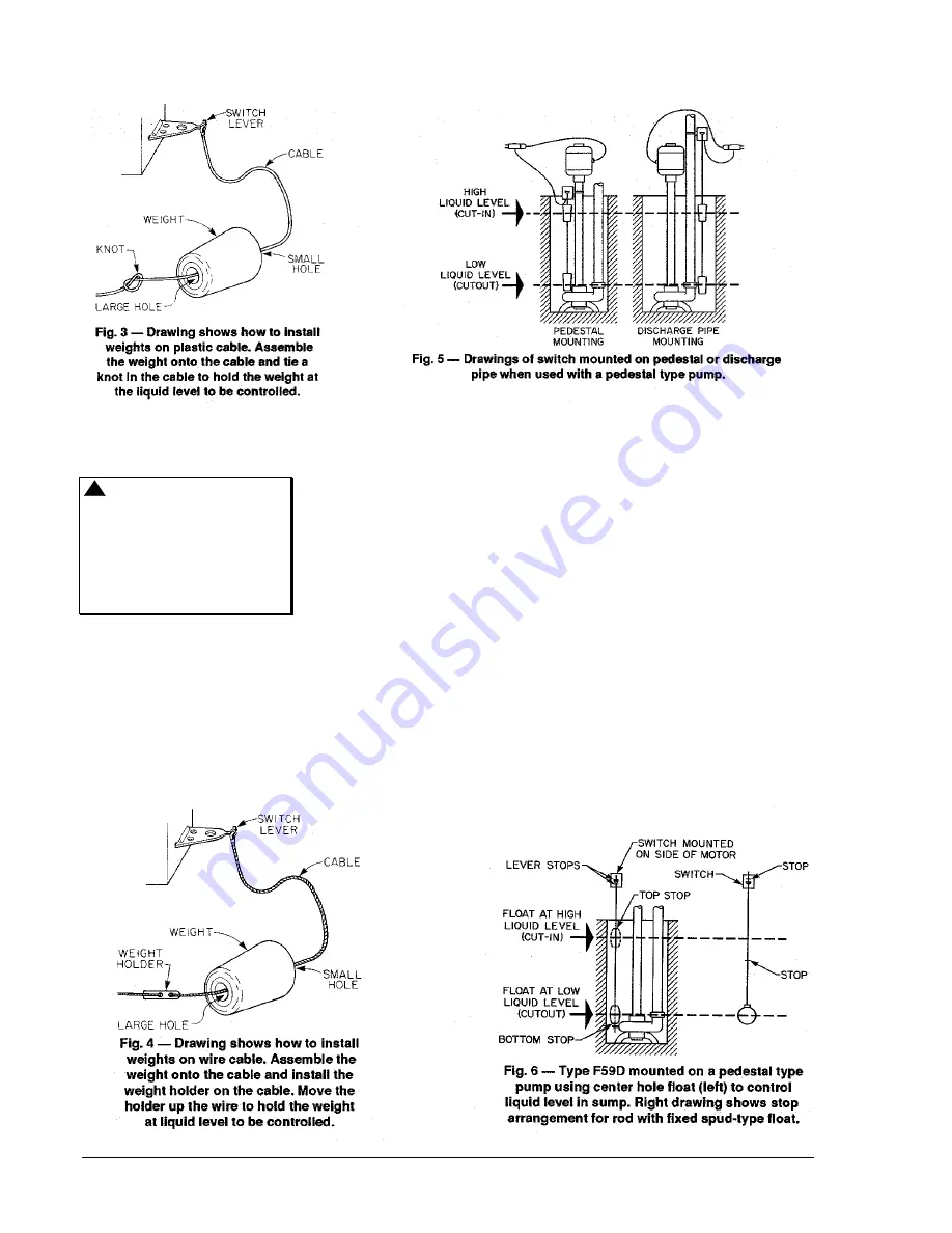
To install weights and cable
proceed as follows:

!

CAUTION:  Do not drop
weights.  The weights could
crack causing them to
waterlog.  This would
prevent the switch from
operating automatically and
would require a new weight
kit.

For Plastic Cable

1.

Place the cable eyelet over
the hook on the switch
lever.  Do not crimp or bend
the switch lever hook.

2.

Thread upper weight onto
plastic cable with large hole
down.

3.

Determine upper liquid level
(pump turn-on level) and tie
a knot in the plastic cable to
support weight at the
selected liquid level.  (See
Fig. 3.)

4.

Slide the weight down over
the knot.

5.

Thread lower weight onto
plastic cable.

6.

Determine lower liquid level
(pump turnoff level) and tie
a knot in plastic cable to
support weight at the
selected liquid level.

7.

Slid the weight down over
the knot.

8.

Cut off excess cable below
lower weight after checking
to be sure weights are at
the correct level.  (See
Fig. 2.)

For Wire Cable

1.

Place the cable eyelet over
the hook on the switch
lever.  Do not crimp or bend
the switch lever hook.

2.

Thread upper weight onto
wire cable.

3.

Thread upper weight holder
onto wire cable to support
weight at the selected liquid
level.  (See Fig. 4.)

Summary of Contents for F59D

Page 1: ... All F59 Series switches are designed for use only as operating controls Where an operating control failure would result in personal injury and or loss of property it is the responsibility of the installer to add devices safety limit controls or systems alarm supervisory systems that protect against or warn of control failure Installation For sump operation mount the switch with the counterbalance...

Page 2: ...t in the plastic cable to support weight at the selected liquid level See Fig 3 4 Slide the weight down over the knot 5 Thread lower weight onto plastic cable 6 Determine lower liquid level pump turnoff level and tie a knot in plastic cable to support weight at the selected liquid level 7 Slid the weight down over the knot 8 Cut off excess cable below lower weight after checking to be sure weights...

Page 3: ...ontacts will remain closed operating lever up when the weight of a float rod only hangs from the operating lever The length of a 1 4 in brass float rod is limited to 3 1 2 feet The float rod should be inserted through the 5 16 in hole in the operating lever Stops should be about 3 8 in apart to prevent binding at the lever IMPORTANT Line up float rod guide and hole in operating lever of switch to ...

Page 4: ... wire to the faceplate screw of the electrical outlet box or to a separate ground wire clamped to a grounded cold water pipe NEVER REMOVE THE CENTER LUG OF THE SWITCH PLUG Grounded cold water pipe must have metal continuity to electrical ground If continuity is interrupted by plastic rubber or other electrical insulating connectors such as hoses fittings washers or gaskets including water meter or...

Reviews: