IFC Networking—Metasys Intelligent Fire Network
47
Commissioning and
Troubleshooting Procedures
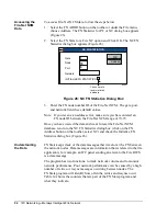
The switches on the MIB enable or disable ground fault detection. SW1
corresponds to Channel A and SW2 corresponds to Channel B.
Switch set On to enable
ground fault feedthrough.
Switch set Off to disable
ground fault feedthrough.
switch
Figure 20: MIB Switches
All network nodes connected to either the N1 LAN or the FN must have a
node address (also referred to as a node number) to identify it on either
one or both of the networks. IFC panels, INAs, Fire-Net NCMs, and
Fire OWSs are all FN nodes. The IFC panels and INAs are only connected
to the FN, while the Fire-Net NCM and Fire OWS are connected to both
the N1 LAN and the FN.
Since they connect to two networks, certain restrictions apply to the
Fire-Net NCM and Fire OWS node addresses. The node addresses for the
Fire OWS and Fire-Net NCM must be:
•
within the ranges specified in the IMPORTANT boxes below
•
the same number on both the N1 LAN and the FN
IMPORTANT:
The Fire-Net NCM must have an FN (Fire Network)
and Metasys Network node address between 70-79.
Fire OWS must have an FN and Metasys Network
node address between 150-159. Addresses above 249
must not be used on the FN.
Setting the
Ground Fault
Switch
Node
Addresses
Summary of Contents for FIRE-MON-17
Page 12: ...12 IFC Networking Metasys Intelligent Fire Network ...
Page 46: ...46 IFC Networking Metasys Intelligent Fire Network ...
Page 58: ...58 IFC Networking Metasys Intelligent Fire Network ...
Page 69: ...IFC Networking Metasys Intelligent Fire Network 69 Notes ...
Page 70: ...70 IFC Networking Metasys Intelligent Fire Network Note ...
Page 71: ...IFC Networking Metasys Intelligent Fire Network 71 Notes ...


