RWF ROTARY SCREW COMPRESSOR UNITS
MAINTENANCE
S70-600 IOM (OCT04)
Page 26
13.
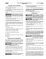
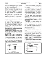
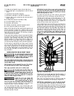
Pack lubrication chamber between
inner ball bearing
and double-row ball bearing in the thrust-bearing assembly
approximately one-half full of multipurpose grease, NLGI #2.
The thrust-bearing assembly will take the remaining space.
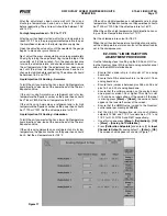
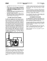
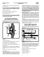
See Figure 21 and 22.
14.
Pack double-row ball bearing with multipurpose grease,
NLGI #2.
GG, HJ, HL
: Install ball bearing into bearing housing with
shield side toward coupling end of shaft. See Figure 21.
Install snap ring into bearing hous ing to retain ball bearing.
This snap ring has a tapered edge to fit tapered groove in
bearing housing. The tapered edge is located away from
ball bearing.
AS, AK, AL
: Install ball bearing into bearing housing. In stall
lip seal in bearing housing end cap. The lip should face to-
wards end of shaft. Put bearing spacer collar in lip seal and
install in bearing housing and tighten setscrews se curely.
See Figure 22.
15.
Insert brass bar or hardwood through port opening be-
tween rotor teeth to keep shaft from turning.
16.
Start thrust-bearing assembly into casing. Turn by hand
until tight. This forces rotor against head. Replace and tighten
locknut or shaft.
17.
Remove brass bar or hardwood from port opening.
18.
Adjust pump end clearance.
BEFORE STARTING PUMP, EN-
SURE THAT ALL DRIVE EQUIP-
MENT GUARDS ARE IN PLACE.
FAILURE TO PROPERLY MOUNT GUARDS MAY RESULT
IN SERIOUS INJURY OR DEATH.
THRUST BEARING ADJUSTMENT
See Figures 21 and 22.
Loosen two screws in face of thrust-bearing assembly.
If shaft cannot be rotated freely, turn thrust-bearing assembly
counterclockwise until shaft can be turned easily.
1.
While turning rotor shaft, rotate thrust-bearing assembly
clockwise until noticeable drag occurs. This is zero end
clearance.
2.
Mark position of bearing housing with respect to the
casing.
3.
Rotate thrust-bearing assembly counterclockwise the
dis tance listed below as measured on outside of bearing
hous ing.
4.
Tighten two setscrews in face of bearing housing after
adjust ment is made to secure thrust-bearing assembly
position.
For viscosities above 2500 SSU, add additional end clear-
ance (0.004" for GG, HJ and HL size pumps and 0.005" for
AS, AK and AL size pumps).
Pump
Distance (in.) on O.D.
End Clearance
Size
of Bearing Housing
(in.)
GG
7/16
.003
HJ, HL
9/16
.003
AS, AK, AL
1/2
.
003
INSTALLATION OF
CARBON GRAPHITE BUSHINGS
When installing carbon graphite bushings, extreme care
must be taken to prevent breaking. Carbon graphite is a
brittle material and easily cracked. If cracked, the bushing will
quickly disinte grate. Using a lubricant and adding a chamfer
on the bushing and the mating part will help in installation.
The additional precautions listed below must be followed for
proper installation:
1.
A press must be used for installation.
2.
Be certain bushing is started straight.
3.
Do not stop pressing operation until bushing is in proper
position. Starting and stopping will result in a cracked
bushing.
4.
Check bushing for cracks after installation.
TROUBLESHOOTING THE DEMAND PUMP
BEFORE OPENING ANY PUMP
LIQUID CHAMBER (PUMPING
CHAMBER, RESERVOIR, JACKET
ETC.) ENSURE:
1. THAT ANY PRESSURE IN CHAMBER HAS BEEN COM-
PLETELY VENTED THROUGH SUCTION OR DISCHARGE
LINES OR OTHER APPROPRIATE OPENINGS OR CON-
NECTIONS.
2. THAT THE DRIVING MEANS (MOTOR, TURBINE,
ENGINE, ETC.) HAS BEEN “LOCKED OUT” OR MADE
NON OPERATIONAL SO THAT IT CANNOT BE STARTED
WHILE WORK IS BEING DONE ON PUMP.
FAILURE TO FOLLOW ABOVE LISTED PRECAUTIONARY
MEASURES MAY RESULT IN SERIOUS INJURY
OR
DEATH.
Mark valve and head before disassembly to ensure proper
reassembly.
If trouble does develop, one of the first steps toward finding
the difficulty is to install a vacuum gauge in the suction port
and a pressure gauge in the discharge port. Readings on
these gauges often will give a clue as to where to start look-
ing for the trouble.
Vacuum Gauge—Suction Port
1.
High reading would indicate:
a. Suction line blocked - foot valve stuck, gate valve
closed, strainer plugged.
b. Liquid too viscous to flow through the piping.
c. Lift too high.
d. Line too small.
2.
Low reading would indicate -
a. Air leak in suction line.
b. End of pipe not in liquid.
c. Pump is worn.
d. Pump is dry - should be primed.
3.
Fluttering, jumping, or erratic reading:
a. Liquid vaporizing.
b. Liquid coming to pump in slugs - possibly an air leak or
insufficient liquid above the end of the suction pipe.
c. Vibrating from cavitation, misalignment, or damaged
parts.


