RWF ROTARY SCREW COMPRESSOR UNITS
MAINTENANCE
S70-600 IOM (OCT04)
Page 31
PRESSURE TRANSDUCERS - TESTING
1.
Shut down the compressor and allow pressures to
equalize.
2.
Isolate suction transducer PE-4 from the unit and depres-
surize.
NOTE: Recover or transfer all refrigerant vapor,
in accordance with local ordinances, before opening to
atmosphere.
3.
Measure the voltage of PE-4 on connector P4 (terminals
WHT and BLK) on the SBC with a digital voltmeter.
4.
The voltage reading should be 1.48 VDC to 1.72
VDC at standard atmospheric pressure (14.7 PSIA or 0
PSIG). When checking transducers at higher elevations, an
allowance in the readings must be made by subtracting ap-
proximately 0.02 VDC per 1000 feet of elevation above sea
level. Therefore, if PE-4 is measured at 5000 feet elevation
under relatively normal weather conditions, the output volt-
age should differ by 0.10 VDC to read between 1.38 VDC
and 1.62 VDC.
5.
Isolate the oil pressure transducer PE-1 from the
package and open it to atmosphere.
6.
Measure the voltage of PE-1 on connector P4
(terminals WHT and BLK) on the SBC.
7.
The voltage reading should be between 1.1 VDC
and 1.29 VDC at standard atmospheric pressure. PE-1, PE-2,
and PE-3 all have a span of 500 PSI as compared to PE-4
with a span of 200 PSI. Therefore, atmospheric pressure
changes have a lesser effect which is 0.0067 VDC per 1000
feet of elevation and 0.00067 VDC per 0.1 inch Hg barometric
deviation.
8.
Isolate transducer PE-2 from the package and
depressurize.
NOTE: Recover or transfer all refrigerant
vapor, in accordance with local ordinances, before open-
ing to atmosphere.
9.
Measure the voltage of PE-2 on connector P4 (terminals
WHT and BLK) on the SBC.
10.
The voltage reading should be between 1.1 VDC and
1.29 VDC at standard atmospheric pressure (see Step 12).
11.
Since the discharge pressure, PE-3, cannot be closed
off from its sensing point (code require ments), close all
transducers from atmosphere and open them to their sens-
ing points so all transducers can equalize to separator pres-
sure.
12.
Measure the voltage of PE-3 on connector P4 (terminals
WHT and BLK) on the SBC.
13.
Measure the voltage of PE-1 on connector P4 (terminals
WHT and BLK) on the SBC.
14.
These two voltages should be within .04 VDC of one
another.
15.
Test is complete.
PRESSURE TRANSDUCERS - REPLACEMENT
1.
Shut off control power.
2.
Close the applicable transducer isolation valve.
NOTE:
To change the discharge pressure transducer (PE-3), it
will be necessary to depressurize the entire compressor
package. Follow "General Instructions For Replacing
Compressor Unit Components" before going to step 3.
3.
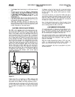
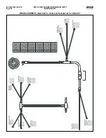
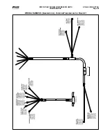
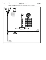
Refer to the WIRING HARNESS section, External
Transducers for Board #1, to identify the wiring harness
connectors.
*
Below 0 PSIG measured in inches of mercury.
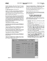
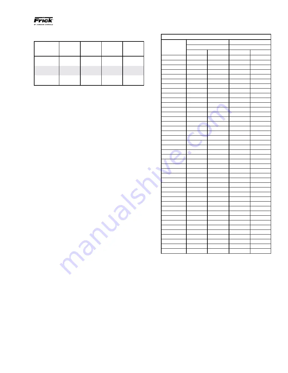
PRESSURE TRANSDUCER CONVERSION DATA
200 psi
500 psi
Sensor
Range - PSI
Range - PSIG*
Voltage
low
high
low
high
1.0
29.92"
9.57"
29.92"
4.10
1.1
29.92"
0.30
29.92"
16.60
1.2
29.92"
5.30
17.10"
29.10
1.3
19.74"
10.30
4.10
41.60
1.4
9.57"
15.30
16.60
54.10
1.5
0.30
20.30
29.10
66.60
1.6
5.30
25.30
41.60
79.10
1.7
10.30
30.30
54.10
91.60
1.8
15.30
35.30
66.60
104.10
1.9
20.30
40.30
79.10
116.60
2.0
25.30
45.30
91.60
129.10
2.1
30.30
50.30
104.10
141.60
2.2
35.30
55.30
116.60
154.10
2.3
40.30
60.30
129.10
166.60
2.4
45.30
65.30
141.60
179.10
2.5
50.30
70.30
154.10
191.60
2.6
55.30
75.30
166.60
204.10
2.7
60.30
80.30
179.10
216.60
2.8
65.30
85.30
191.60
229.10
2.9
70.30
90.30
204.10
241.60
3.0
75.30
95.30
216.60
254.10
3.1
80.30
100.30
229.10
266.60
3.2
85.30
105.30
241.60
279.10
3.3
90.30
110.30
254.10
291.60
3.4
95.30
115.30
266.60
304.10
3.5
100.30
120.30
279.10
316.60
3.6
105.30
125.30
291.60
329.10
3.7
110.30
130.30
304.10
341.60
3.8
115.30
135.30
316.60
354.10
3.9
120.30
140.30
329.10
366.60
4.0
125.30
145.30
341.60
379.10
4.1
130.30
150.30
354.10
391.60
4.2
135.30
155.30
366.60
404.10
4.3
140.30
160.30
379.10
416.60
4.4
145.30
165.30
391.60
429.10
4.5
150.30
170.30
404.10
441.60
4.6
155.30
175.30
416.60
454.10
4.7
160.30
180.30
429.10
466.60
4.8
165.30
185.30
441.60
479.10
4.9
170.30
190.30
454.10
491.60
5.0
175.30
195.30
466.60
504.10
At 0 psig
1.094 V
1.494 V
0.968 V
1.268 V
BONNET CAP SCREW TORQUE VALUES
Valve
Valve
Screw
Size
Torque
Size
Torque
Size
DN (mm)
(Nm)
ANSI
(lb-ft)
(mm)
65
74
2 1/2"
54
M12
80
44
3"
32
M10
100
74
4"
54
M12
125
183
5"
134
M16
150
183
6"
134
M16
200
370
8"
271
M20

