RWF ROTARY SCREW COMPRESSOR UNITS
MAINTENANCE
S70-600 IOM (OCT04)
Page 39
SHUTDOWN DUE TO IMPROPER OIL
PRESSURE (HIGH STAGE and BOOSTER)
The compressor must not operate with incorrect oil
pressure.
1.
Refer to CONTROL SETUP - "OIL SETPOINTS DISPLAY"
in S90-010 O.
MOTOR REPLACEMENT
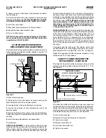
The following procedure is required when a motor is replaced
in the field.
1.
Verify that main power to the unit is disconnected and
tag the switch.
2.
Disconnect the coupling from the motor shaft.
3.
Remove the two bolts from the motor feet.
4.
While supporting the motor with a crane, remove the eight
bolts connecting the motor to the tunnel, then remove the
motor.
5.
Thoroughly clean the motor feet and mounting pads of
burrs and other foreign matter to ensure firm seating of the
new motor.
6.
While supporting the new motor with the crane, install and
hand tighten the eight bolts to connect the motor to the tunnel.
Then torque the bolts in a star pattern to 250 ft-lb.
7.
Then install the two bolts in the in the motor feet and torque
them to 250 ft-lb. Remove the crane from motor.
8.
Reattach coupling to the motor.
BARE COMPRESSOR REPLACEMENT
The following procedure is required only when a bare com-
pressor is replaced in the field.
1.
Verify that main power to the unit is disconnected and
tag the switch.
2.
Remove all tubing, piping, and wiring that is connected
to the compressor.
3.
Disconnect the coupling from the motor shaft.
4.
While supporting the motor and compressor assembly with
a crane, remove the bolts at the motor feet, compressor feet,
and separator flange.
5.
Thoroughly clean the compressor and motor feet and
mounting pads of burrs and other foreign matter to ensure
firm seating of the compressor.
6.
Clean the discharge flange surfaces on the compres sor
and separator.
7.
Set the assembly on a clean surface and remove the two
pins and bolts connecting the compressor to the tunnel and
remove the compressor.
8.
Assemble the new compressor to the tunnel by inserting
the two pins and hand tightening the bolts. then torque the
bolts in a star pattern to 250 ft-lb.
9.
Install a gasket on the compressor discharge connec tion
of the separator.
10.
Using the crane, set the new assembly in place and shim
the motor and compressor feet wherer required.
11.
Reattach the drive coupling.
12.
The shaft alignment must be checked and tolerances
verified with the Frick service dept.
13.
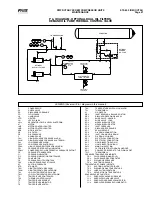
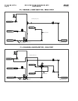
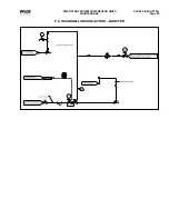
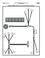
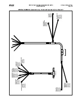
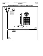
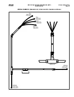
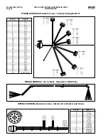
Complete tubing, piping and wiring per the P & I and
wiring diagrams.
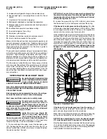
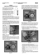
Install the valve and adjust the spring tension accordingly
to maintain the predetermined oil temperature. The rec-
ommended oil temperatures are 130°F for ammonia and
140°F for R-22. Check with Frick service for recommended
oil temperatures for other refrigerants.
If all of the above steps have been properly performed and
the desired oil temperature can not be achieved, contact
Frick Service.

