RXB PLUS ROTARY SCREW COMPRESSOR UNITS
INSTALLATION
070.101-IOM (JAN 13)
Page 13
HIGH
PRESSURE
LIQUID
INTERMEDIATE PRESSURE
GAS TO COMPRESSOR
SUCTION
STR
VCK
SUBCOOLED
HIGH PRESSURE
LIQUID TO
EVAPORATOR
ECONOMIZER
COOLER
ECON1
HV-2
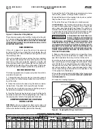
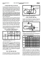
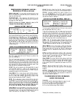
Figure 15 - Shell And Coil Economizer System
HIGH
PRESSURE
LIQUID
INTERMEDIATE PRESSURE
GAS TO COMPRESSOR
SUCTION
STR
VCK
SUBCOOLED
HIGH PRESSURE
LIQUID TO
EVAPORATOR
ECONOMIZER
COOLER
WIRING
ECON2
HV-2
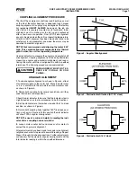
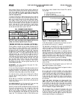
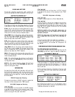
Figure 16 - Direct Expansion Economizer System
HIGH
PRESSURE
LIQUID
INTERMEDIATE PRESSURE
GAS TO COMPRESSOR
SUCTION
STR
VCK
CONTROLLED
PRESSURE
SATURATED LIQUID
TO EVAPORATOR
ECONOMIZER
VESSEL
BPR
ECON3
HV-2
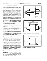
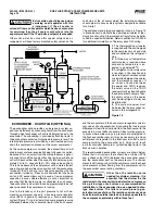
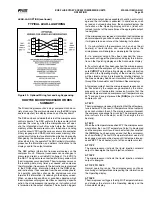
Figure 17 - Flash Economizer System
INTERMEDIATE PRESSURE
GAS TO COMPRESSOR
SUCTION
STR
VCK
BPR
CONTROLLED PRESSURE
SATURATED LIQUID TO EVAPORATOR
ECONOMIZER
VESSEL
ECON4
HV-2
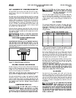
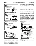
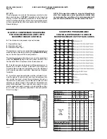
Figure 18 - Multiple Compressor Economizer System
For.refrigeration.plants.employing.multiple.compressors.on.
a.common.economizing.vessel,.regardless.of.economizer.
type,.each.compressor.must.have.a.back-pressure.regulat-
ing.valve.in.order.to.balance.the.economizer.load,.or.gas.
flow,.between.compressors..The.problem.of.balancing.load.
becomes.most.important.when.one.or.more.compressors.
run.at.partial.load,.exposing.the.economizer.port.to.suction.
pressure..In.the.case.of.a.flash.vessel,.there.is.no.need.for.
the.redundancy.of.a.back-pressure.regulating.valve.on.the.
vessel.and.each.of.the.multiple.compressors..Omit.the.BPR.
valve.on.the.flash.economizer.vessel.and.use.one.on.each.
compressor,.as.shown.in.Figure.18.
ELECTRICAL
NOTE: Before proceeding with electrical installation,
read the instructions in the section “Proper Installation
of Elec tronic Equip ment in an Industrial Environment”.
RXB. PLUS. units. are. supplied. with. a. SBC. (single-board.
computer). microprocessor. control. system.. Care. must. be.
taken.that.the.controls.are.not.exposed.to.physical.damage.
during.handling,.storage,.and.installa.tion..The.microproces-
sor.enclosure.cover.must.be.kept.tightly.closed.to.prevent.
entry.of.moisture.and.foreign.matter.
Customer-control power connec-
tions are made at the BOTTOM of
the microprocessor enclosure.
Consult local ordinances before installation. Current
transformer wiring should be kept separate. Extreme
care should be taken that metal filings or other foreign
material is not left in the microprocessor enclosure. Use
seal-tight conduit fittings to prevent moisture entry into
the microprocessor enclosure. This is the ONLY electri-
cal enclo sure that should be opened during installation
and it should be kept tightly closed whenever work is
not being performed in it.
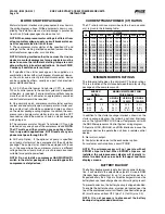
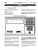
Figure 19
NOTE: Customer ground required, see Micro Panel As-
sembly Wiring Diagram.


