RXB PLUS ROTARY SCREW COMPRESSOR UNITS
INSTALLATION
070.101-IOM (JAN 13)
Page 14
MOTOR STARTER PACKAGE
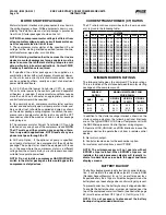
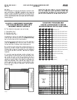
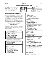
Motor.starter.and.interlock.wiring.requirements.are.shown.in.
the.wiring.diagram,.above..All.the.equipment.shown.is.sup-
plied.by.the.installer.unless.a.starter.package.is.pur.chased.
from.Frick...Starter.packages.should.consist.of:
NOTE: When compressor mo tor vol tage is dif fer ent from
oil pump mo tor vol tage, supply a circuit breaker discon-
nect for separate feed in lieu of fuses.
1.
.The. compressor. motor. starter. of. the. specified. HP. and.
voltage. for. the. starting. method. specified. (across-the-line,.
autotransformer,.wye-delta,.or.solid.state).
NOTE: If starting methods other than across-the-line are
desired, a motor/compressor torque analysis must be
done to ensure that sufficient starting torque is avail-
able, particularly in booster applica tions. Contact FRICK
Company if assistance is required.
2.
. If. specified,. the. starter. package. can. be. supplied. as. a.
combination.starter.with.circuit.breaker.disconnect..Howev-
er,. the. motor. overcurrent. protection/disconnection. device.
can.be.supplied.by.others,.usually.as.a.part.of.an.electrical.
power.distribution.board.
3.
. A. 2.0. KVA. control. power. transformer. (CPT),. to. supply.
120.volt.control.power.to.the.control.system.and.separator.
oil.heaters,.is.included..If.environmental.conditions.require.
more.than.a.500.watt.oil.heater,.an.appro.priately.oversized.
control.trans.former.will.be.required.
4.
.One.normally.open,.compressor-motor-starter.auxiliary.
contact.and.one.normally.open,.oil-pump-motor-starter.aux-
iliary.con.tact.(opt.).should.be.supplied.and.wired.as.shown.
on.the.starter.package.wiring.diagram..In.addition,.the.com-
pressor.and.oil.pump.motor.starter.(opt.).coils.and.the.CPT.
secondaries.should.be.wired.as.shown.on.starter.package.
wiring.diagram.
5.
.The.compressor.motor.Current.Transformer.(CT).can.be.
installed.on.any.one.phase.of.the.compressor.leads..
NOTE:
The CT must see all the current on any one phase; there-
fore in wye-delta applications, BOTH leads of any one
phase must pass through the CT.
6.
.Oil.Pump.Option:..If.the.optional.oil.pump.is.specified,.
an.oil.pump.starter.must.be.a.com.ponent.of.the.unit.starter.
package..The.pump.starter.should.be.equipped.with.fuses.
or,.in.the.case.where.the.compressor.motor.is.a.different.
voltage.from.the.oil.pump.motor,.a.circuit.breaker.disconnect.
suitable.for.separate.power.feed.
NOTE: Do not install a compressor HAND/OFF/AUTO
switch in the starter package as this would bypass the
compressor safety devices.
CURRENT TRANSFORMER (CT) RATIOS
The.CT.ratio.for.various.motor.sizes.(with.a.5.amp..second-
ary).is.given.in.the.following.table:
VOLTAGE
HP
200
230
380
460
575
2300 4160
20
100:5
100:5
100:5
100:5
100:5
-
-...
25
100:5
100:5
100:5
100:5
100:5
-
-...
30
200:5
100:5
100:5
100:5
100:5
-
-...
40
200:5
200:5
100:5
100:5
100:5
-
-...
50
200:5
200:5
100:5
100:5
100:5
-
-...
60
300:5
200:5
200:5
100:5
100:5
-
-...
75
300:5
300:5
200:5
200:5
100:5
-
-...
100
400:5
300:5
200:5
200:5
200:5
-
-...
125
500:5
400:5
300:5
200:5
200:5
-
-...
150
500:5
500:5
300:5
300:5
200:5
-
-...
200
800:5
600:5
400:5
300:5
300:5
100:5
50:5.
250
800:5
800:5
500:5
400:5
300:5
100:5
50:5
MINI MUM BURDEN RATINGS
The.following.table.gives.the.minimum.CT.burden.ratings..
This.is.a.function.of.the.distance.between.the.motor.starting.
package.and.the.compressor.unit.
BURDEN
RATING
MAXIMUM DISTANCE FROM
FRICK PANEL
ANSI
VA
USING #
14 AWG
USING #
12 AWG
USING #
10 AWG
B-0.1
2.5
15.ft
25.ft
40.ft
B-0.2
5
35.ft
55.ft
88.ft
B-0.5
12.5
93.ft
148.ft
236.ft
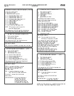
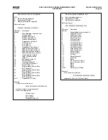
In.addition.to.the.starter.package.interlocks.shown.on.the.
starter. package. diagram,. the. following. optional. interlocks.
are.on.the.typical.RXB.PLUS.Screw.Compressor.unit.with.
the.SBC.Microprocessor.Control.System.wiring.diagram:
1.
.Remote.LOAD,.UNLOAD,.and.RUN.interlocks.in.case.the.
customer.desires.to.operate.the.unit.from.a.remote.control.
device.
2.
.Alarm.Horn.output.
3.
.Control.solenoid.valve.for.the.economizer.option.
For.customer.control.options,.consult.FRICK.
NOTE: The microprocessor will not operate without
EPROM chips installed. When EPROM chips are not
installed, the microprocessor display will typically in-
dicate two dark lines across both the upper and lower
display screens.
BATTERY BACKUP
The.battery.backup.prevents.data.loss.during.power.interrup-
tion..It.will.maintain.the.adjustable.setpoints.stored.in.RAM.
(Random.Access.Memory).for.up.to.1.year.after.power.loss..
Expected.battery.life.is.10.years..A.trickle.charge.maintains.the.
battery.backup.at.peak.charge.when.control.voltage.is.present.
To.prevent.power.loss,.the.battery.backup.is.shipped.disabled..
To.enable.the.battery.backup,.a.jumper.pin.located.near.the.
top.of.the.microprocessor.circuit.board.(see.illustration.page.
52).must.be.moved.from.OFF.(pins.1-2).to.ON.(pins.2-3).
NOTE: It is not necessary to disconnect the battery
backup during extended downtime.


