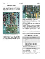
background image

VYPER

 VARIABLE SPEED DRIVE

OPERATION

S100-200 IOM (MAY 08)

Page 29

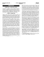
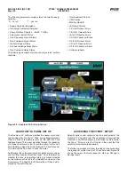
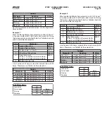
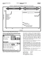
Figure 33 - Home Screen Service Level 2: Press the [Menu] Button then Select Operating Values from the Flydown

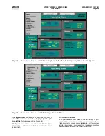
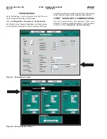
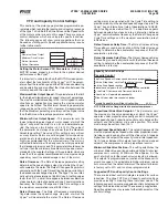
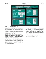
Figure 34 - Home Screen Service Level 2: Select Vyper From the Menu

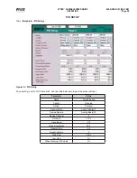
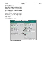
The 

[Vyper]

 selection leads to an additional fl yout menu 

where the user can select either the 

[Vyper]

 or the 

[ Har-

monic Filter]

 setup screens (See Figure 35).

The  fl ydown menu allows the user to select either the Vyper


Drive setup or, if the  Harmonic Filter is installed, the display 
information.

THE VYPER

 SCREEN 

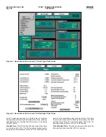
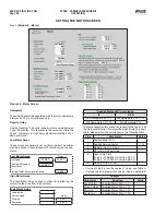
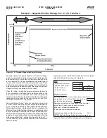
The Vyper Screen Level 2 (See Figure 36) displays Vyper


system status including  operational parameters such as 
internal currents, voltages, and temperatures. It also gives 
detailed information on some external equipment such as 
the  circulation pump and the  motor temperature.

Summary of Contents for Frick vyper VYA PG -46

Page 1: ... 3c THIS MANUAL CONTAINS RIGGING ASSEMBLY START UP AND MAINTENANCE INSTRUCTIONS READ THOROUGHLY BEFORE BEGINNING INSTALLATION FAILURE TO FOLLOW THESE INSTRUCTIONS COULD RESULT IN DAMAGE OR IMPROPER OPERATION OF THE UNIT 305 254 Horsepower 437 362 Horsepower Please check www johnsoncontrols com for the latest version of this publication ...

Page 2: ... SYSTEM OPERATING CONDITIONS 10 PNEUMATIC CONTROLS 10 VYPER SYSTEM OVERVIEW 10 CONFIGURATION 14 VYPER COOLING LOOP 14 Liquid Cooled Vyper P I Diagram Economized 15 Liquid Cooled Vyper P I Diagram Noneconomized 16 PACKAGE MOUNTED VYPER 17 VYPER PREINSTALLATION SITE CHECKLIST 18 BLOWER MOTOR ROTATION 18 POWER AND CONTROL WIRING ENTRY LOCATIONS19 EXTERNAL POWER AND CONTROL WIRING 20 ELECTRICAL CONDUI...

Page 3: ...lectronic con trol equipment All safety precautions consistent with opera tion of high current and voltage electrical equipment should be strictly enforced JOB INSPECTION Immediately upon arrival examine all crates boxes and exposed compressor and component surfaces for damage Unpack all items and check against shipping lists for any possible shortage Examine all items for damage in transit TRANSI...

Page 4: ...allic no PVC or other materials are permitted RIGGING AND HANDLING The Vyper cabinet unit is best moved via lifting lugs on the top sides of the cabinet Special care must be exercised not to damage the pump or peripheral equipment on the rear of the cabinet Never move the unit by pushing or forking against the Vyper Cabinet FRICK VYPER MODELNUMBER DEFINITIONS VYA_RGF_46 Input Voltage 46 460V 50 40...

Page 5: ...e operating frequency range of the drive The unit is started with the compressor fully unloaded until the frequency reaches the minimum operating frequency range In addition the drive is capable of operating without a load for ease of service Overload 105 of full load for 7 seconds Efficiency 98 Typical at rated load and frequency INPUT SHORT CIRCUIT LIMITS The Vyper can be affected by specific ev...

Page 6: ... units with motor power lead lengths between 3 to 50 feet Adequate service clearances including door swing must be maintained around the Vyper Care should be taken to ensure that the Vyper and it s associated piping and wiring do not obstruct the access to service areas Liquid supply cooling temperature requirements vary be tween Water and Glycol cooled units The required flow rate is based on the...

Page 7: ...NGER PRESSURE DROP In order to adequately size piping and booster pump require ments the pressure drop of the coolant across the heat Figure 3 Minimum Flow Rates GLYCOL exchanger must be known Figure 4 provides installation designers with pressure drop reference for different mixtures of propylene glycol and water ...

Page 8: ... wiring is unshielded it needs to be in metallic or PVC metallic conduit Do not use a cable insulation thickness of 15 mils 0 015 in or less Use copper wire only NO aluminum power wiring is permitted Wire gauge requirements and recommendations are based on 75 degrees C 167 F Wire gauge is not to be reduced if using higher temperature wire An acceptable example of unshielded wiring is THHN or TWHN ...

Page 9: ...ply transformer With a VSD there is no way to know in advance whether the capacitors will cause interference When aVSD is started and there are problems cause by power factor capacitors it will be necessary to remove those capacitors In some installations capacitors are switched on line as power factor drops The switching transients created by connecting and discon necting power factor capacitors ...

Page 10: ... prelube cycle It also provides fast disconnect from the AC line The SCR trigger board provides the turn on and turn off commands for the SCRs The Vyper logic board provides commands to the SCR trigger board during precharge THE DC LINK FILTER SECTION of the drive consists of a series of electrolytic filter capacitors C1 C6 These capaci tors provide a large energy reservoir for use by the DC to AC...

Page 11: ...E SPEED DRIVE INSTALLATION S100 200 IOM MAY 08 Page 11 Figure 6 Vyper Elementary Wiring Diagram NOTE Drawings for specific units can be found in the door of the Vyper drive or check with Frick Engineering department ...

Page 12: ...POWER UNIT is the most complicated power component in the optional filter Its purpose is to generate the harmonic currents required by the Vyper AC to DC converter so that these harmonic currents are not drawn from the AC line The Filter Power Unit is identical to the Vyper Power Unit except for two less capacitors in the filter capacitor bank C13 C16 a smaller IGBT module 2MOD mounted to a liquid...

Page 13: ...VYPER VARIABLE SPEED DRIVE INSTALLATION S100 200 IOM MAY 08 Page 13 Figure 8 Harmonic Filter Elementary Wiring Diagram NOTE Typical Check with engineering for latest drawings ...

Page 14: ...temperature reading These wil also be factory set for a Low Temp alarm and shutdown at 85 F and 80 F with a 90 second delay when running The High Temp Alarm and shutdown will be factory set at 125 F and 130 F with a 30 second delay when running If the Vyper coolant temperature drops too low condensation may occur damaging vital electronic components In addi tion to controlling the Vyper cabinet co...

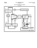
Page 15: ...VYPER VARIABLE SPEED DRIVE INSTALLATION S100 200 IOM MAY 08 Page 15 Liquid Cooled Vyper P I Diagram Economized ...

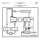
Page 16: ...VYPER VARIABLE SPEED DRIVE INSTALLATION S100 200 IOM MAY 08 Page 16 Liquid Cooled Vyper P I Diagram Noneconomized ...

Page 17: ...er cabinet mounted on a Frick RWF II 134 refrigeration package Individual systems configurations will vary according to model and horsepower sizes selected The Vyper cabinet is mounted on a rectangular welded steel channel which provides both an attachment point for the cabinet s side brackets and also helps to maintain the rigidity of the cabinet during service The channel assembly VSD cabinet is...

Page 18: ...ccordance with local and national electrical codes and current safety standards See Power wiring section for more details Verify that the power cable lengths from the Vyper to the compressor motor do not exceed 50 feet Verify that motor is suitable for Inverter duty service 20 100 speed Motor must have thermal protection per NEC 2005 RTD Thermostat Thermister Verify that ambient temperature remain...

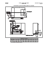
Page 19: ...8 Page 19 Dimensions in Inches Drive HP A B C D E F G H J K 305 254 1 63 4 50 9 00 6 38 4 38 35 00 5 50 3 56 6 63 2 00 437 362 6 63 6 75 10 13 2 00 3 25 40 53 2 25 3 00 13 00 2 00 Contact factory for detailed dimensions POWER AND CONTROL WIRING ENTRY LOCATIONS ...

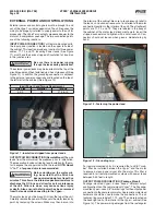
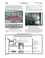
Page 20: ...tain that the Drive has been powered down for at least five minutes This allows the internal capacitors resistors to discharge the DC bus and allow for safe maintenance of the unit Failure to do so may cause serious injury or death Also ensure that all power has been removed from the leads while connecting to the Vyper The motor leads must be brought in from the top of the unit Carefully remove th...

Page 21: ...ssion 216 240 in lb ELECTRICAL CONDUITS All power wiring must be contained in metallic conduit All compressor motor wiring must be in a separate metallic conduit Oil pump motor wiring must be in a separate metallic conduit Compressor motor cooling fan power must be in a separate metallic conduit Control wiring between the Quantum LX panel and the Vyper must be contained in separate metallic condui...

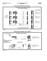
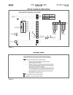
Page 22: ...VYPER VARIABLE SPEED DRIVE INSTALLATION S100 200 IOM MAY 08 Page 22 MOTOR RTD THERMAL PROTECTION Figure 17 TEMPERATURE CONTROL VALVE WIRING Figure 18 ...

Page 23: ...VYPER VARIABLE SPEED DRIVE INSTALLATION S100 200 IOM MAY 08 Page 23 MOTOR COOLING BLOWER WIRING Figure 19 Figure 20 DRAWING NOTES ...

Page 24: ...VYPER VARIABLE SPEED DRIVE INSTALLATION S100 200 IOM MAY 08 Page 24 ANALOG BOARD WIRING Figure 21 ...

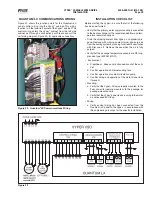
Page 25: ... fans c Confirm operation of coolant circulation pump d Confirm wiring and operation of the motor blower fans if present Mounting a Verify that the Vyper Drive is properly mounted to the floor or wall for remote mounts or to the package for package mounted units b Verify that theVyper power leads running to the motor do not exceed 50 ft long Wiring a Verify control wiring has been connected from t...

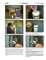
Page 26: ... proper electrical connections as discussed in previous sections The Vyper setup consists of three primary requirements Cooling Loop Fluid Preparation Quantum LX Panel Setup Job FLA Trim Pot Adjustment COOLANT REPLACEMENT ALWAYS WEAR EYE PROTECTION WHEN SERVICING THE COOLING CIRCUIT OF THE VYPER The Vyper is shipped from the factory with a premixed shipping fluid which contains a rust inhibitor th...

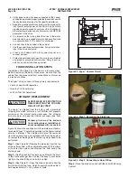
Page 27: ... until the fluid level remains constant about one inch form the top of the manifold See Figure 30 Figure 30 Step 6 Top Off the Cooling System Figure 31 Step 7 Replace the Pipe Plug and Tighten Step 7 Replace and tighten the plug on the top of the mani fold using an adjustable wrench See Figure 31 Figure 32 Step 8 Insert Plug J2 to Stop Coolant Pump Step 8 Insert plug J2 into the logic board to sto...

Page 28: ...differential pressure the motor speed will increase to meet the capacity requirement When the slide valve reaches the Capacity Control Slide Valve setpoint the motor speed can increase At this point the slide valve and motor speed can continue to increase independently of one another until the capacity requirement is met or they reach their maximum values If the compressor is in Auto mode the moto...

Page 29: ...ser can select either the Vyper or the Har monic Filter setup screens See Figure 35 The flydown menu allows the user to select either theVyper Drive setup or if the Harmonic Filter is installed the display information THE VYPER SCREEN The Vyper Screen Level 2 See Figure 36 displays Vyper system status including operational parameters such as internal currents voltages and temperatures It also give...

Page 30: ...earing theVSD memory and resetting the kWh record Standby Time The VSD enters Standby mode when there is no load on the VSD The VSD capacitor banks remain charged and the compressor output is 0 Hz Standby mode permits fast acceleration when the load returns If the time of zero load surpasses the Standby time setting the VSD will need to go through a restart sequence The values for Standby mode can...

Page 31: ...s indicate the status of the field They are displayed as the following 0 no off 1 yes on VSD Operating Mode Harmonic Filter Present Harmonic Filter Operating Mode Water Pump Energized Precharge Relay Energized Trigger SCRs Energized HARMONIC FILTER SCREEN The Harmonic Filter screen See Figure 37 shows important aspects of the IEEE519 Harmonic Filter in action In addi tion to current and voltage in...

Page 32: ...compressors via the SFS 229 Frick Interface Board This is accomplished through the reception of a Speed Command value in rotations per minute and a Run Command signal from the Quantum LX control panel This data will then be used to drive the motor Additionally the software will monitor motor current values and fault flags received from the Vyper Drive to determine whether the drive is operating sa...

Page 33: ...sion The screen shown in Figure 39 will appear Type 2 into the User Level field Enter Level 2 password Return to the menu and the Home screen The home screen will now provide additional information as shown in Figure 40 Figure 39 Setting User Level Figure 40 Home Screen After Changing to Service Level 2 ...

Page 34: ...apacity Regulations and Package spe cific information Verify that Screw Compressor with Vyper is selected under the package Drive field This will allow the Vyper specific screens to be displayed See Figure 41 VYPER QUANTUM LX COMMUNICATIONS Set the Communications rate between Vyper and Quantum LX Make sure that the Comm 1 is set as shown in Figure 42 Press Setpoints Communications Figure 41 Config...

Page 35: ... PID Channel 5 Use the table below to program the proper settings Parameter Value Name Drive Cooling Control Running Action Forward Control Point Vyper Coolant Device Source Analog Board 2 Device Channel 1 Setpoint 110 F Dead Band 0 F Proportional Band 20 F Integral Gain 5 0 Derivative Gain 0 High Limit 100 Low Limit 0 When Running OFF Value 0 ...

Page 36: ...ting the motor and the drive from high currents High Motor Amps Load Inhibit Force Unload Delay Warning 5 SEC Shutdown 5 SEC Applied Motor FLA Calculation IF USE Mtr Nameplate SF 1 0 Mtr Nameplate FLA 1 15 Mtr Nameplate SF 1 15 Mtr Nameplate FLA There are several safety scenarios regarding the Vyper and the motor combination To determine which strategy is appli cable please follow the calculations...

Page 37: ...d Inhibit Applied Motor FLA x 1 1 374 A Force Unload Applied Motor FLA x 1 12 380 A Warning Applied Motor FLA x 1 13 384 A Shutdown Applied Mtr FLA x 1 15 391 A High Motor Amps Load Inhibit 357 Force Unload 374 Delay Warning 381 5 SEC Shutdown 389 5 SEC Example 2 What are the High Motor Amp setpoints if a 437 HP Vyper is to drive a motor with 1 15 SF and a 534 Amp FLA Using the Values determine wh...

Page 38: ...33 A Shutdown Applied Mtr FLA x 1 15 339 A High Motor Amps Load Inhibit 310 Force Unload 324 Delay Warning 330 5 SEC Shutdown 337 5 SEC Example 4 What are the High Motor Amp setpoints if a 437 HP Vyper is to drive a motor with 1 00 SF and a 552 A FLA Using the Values determine whether Table A or Table B should be used to calculate the setpoints SF 1 00 motors need to be derated by dividing the Nam...

Page 39: ...nd Cycle Time settings and the maximum acceleration rate of 6 08 Hz sec Rate of Decrease The Rate of Decrease parameter set ting determines the speed change step size at which the Vyper will decelerate the motor The Rate of Decrease setting works in conjunction with the Cycle Time setting to provide variability in the desired speed change step rate The Vyper has an internally set rate of decelerat...

Page 40: ...own applications The Variable Speed Minimum Slide Valve Position is a factory default and is related to the Minimum Drive Output setting However an additional control feature is needed to override the Variable Speed Minimum Slide Valve Position setting in order to keep the Slide Valve loaded at a much higher level Frick recommends that the slide valve position for 5 1 applications be set as high a...

Page 41: ...hen selecting Setpoints and Compressor Press the ENTER key to advance to the Compressor Safeties Screen Step 2 Refer to Figure 47 Use the cursor arrow and Tab keys to navigate to the Highest Capacity To Permit Starting Callout 1 and Compressor Automatic Mode Minimum Capacity Callout 2 Use the keypad to program the setpoints to 97 Press the Enter key to accept the value for each field Step 3 Press ...

Page 42: ...gure 48 This control strategy is a variation on the generic control strategy described previously Not all applications require or are suitable for the very low speeds obtainable by the Vyper drive Many times the motor is the limiting factor and is not suitable for 20 speed but is capable of 50 speed For these applications the settings within the Quantum LX can assure that the motor never runs slow...

Page 43: ... proportional component over every 30 sec onds to drive the actual value back to the Capacity Control setpoint If the actual value remains 21 psig the Integration Time Setpoint would increase the drive output to 100 over 1 5 minutes See Figure 50 This control strategy is a variation on the generic control strategy shown previously Not all applications require or are suitable for the very low speed...

Page 44: ...A 2 Motor Service Factor 1 15 3 Multiply Line 1 x Line 2 4 HP Rating of Vyper Drive 5 Vyper Amp Limit If Line 4 is 305 254 HP Value is 380 A If Line 4 is 437 362 HP Value is 565 A 6 Multiply Line 5 x 1 05 See SETTING THE MOTOR SCREEN section Table D Job FLA Calculation If in Table C Job FLA Line 3 is Less than Line 6 Line 3 Line 3 is greater than Line 6 Line 5 Adjust the trim pot on the Vyper Logi...

Page 45: ...2 Closed 6 Open 1 Closed 5 Open 4 Open 3 Open Open 2 Open 1 Open FRICK INTERFACE BOARD DIP SWITCH SETTINGS Used before Jan 2008 On the Frick Interface Board Figure 54 on the Vyper right door there is a dip switch array The array is located at the upper right of the FIB as shown in the photograph below This dip switch array must be set correctly for the Vyper to operate properly The switches should...

Page 46: ...dicators RX TX Logic 7 Board to Quantum LX J16 Communications Cable Logic 8 Board to Quantum LX Communications Indicators RX TX 9 Logic Board to Filter Board J15 Communications Cable Logic 10 Board to Filter Board DC Bus Voltage Input 11 J2 Remove to manually engage circula 12 tion pumps and internal fans JOB FLA Potentiometer 13 Frequency Switch 60 50Hz 14 Output Current input Phase A B C 15 The ...

Page 47: ...the cooling system and oxidizing the aluminum If any of these conditions exist the coolant may have bacteria growth Take proper health precautions when draining the coolant Drain the coolant and blow the system out with compressed air Flush the coolant system out thoroughly with water Fill the coolant loop with Ethylene Glycol Not Propylene Glycol Circulate the Ethylene Glycol for one hour Drain t...

Page 48: ...utput current This is due to the power factor at the input to the Vyper being greater than 0 95 and nearly unity when the Harmonic filter option is included Motor FLA must be measured at the motor terminals where the power factor is the normal motor power factor Use the true RMS reading meter to make the measurements On the Remote mountedVyper compressor drive what is the dV dt snubber filter for ...

Page 49: ...Vyper screens that are not covered in this manual In addition to this manual it is strongly recommended that you have the Installation Operation and Maintenance manual to the specific refrigeration system which will be controlled by the Frick Vyper VYPER ALARMS SHUTDOWNS In addition to the Alarms and Shutdowns that the Quantum LX software generates for the basic compressor package the Vyper unit h...

Page 50: ...ens the K1 relay on the Vyper Logic board When the relay opens FRICK VYPER FAULT CODES Quantum LX Failure Code Quantum LX Failure Message 1 VSD Interface Board Power Supply Fault 2 VSD Interface Board Loss of Motor Current 3 VSD Interface Board Motor Current 15 4 VSD Interface Board Run Signal Fault 5 VSD Interface Board to Panel Comms Loss 7 VSD Initialization Fault 8 VSD Stop Contacts Fault 9 Ha...

Page 51: ... shall each be compared in software to a limit of 175 F 79 C and if this limit is exceeded the unit shall initiate a safety shutdown The fan s and water pump shall remain energized until the inverter power module baseplate temperature falls below 165 F The fans and pumps shall be de energized when all baseplate temperatures drop below their reset thresholds Fault 12 High Phase C Inverter Baseplate...

Page 52: ...xcept applying to Phase B Gate Driver Fault 23 Vyper Phase C Gate Driver Message Quantum Fault 23 Quantum LX VSD Phase C Gate Driver Fault Same comments as Fault 21 except applying to Phase C Gate Driver Fault 24 Vyper Single Phase Input Power Message Quantum Fault 24 Quantum LX VSD Single Phase Input Power Fault TheVyper s SCRTrigger Control board contains circuitry that checks the three phase ma...

Page 53: ... equally from the junction of the center or series capacitor connection to the negative bus and to the positive bus This center point should be ap proximately of the total DC link voltage If the voltage is greater than 88 VDC from the of the total DC link voltage then this shutdown will occur First verify the operation of the DC bus voltage isolation board and all associated wiring to the Vyper Lo...

Page 54: ...nuity at Vyper Logic board plug J2 Also make certain that one side of the circuit is not shorted to the enclosure Fault 42 Vyperdrive Serial Communication Message Quantum Fault 42 Quantum LX VSD Serial Communications Fault When requesting Status data the response data from the Vyper includes a bit that indicates whether communications were lost from the Frick Interface Board to the Vyper If this b...

Page 55: ...bus structure verify the wiring between the Vyper Logic board and Quantum LX Vyper trigger board and the input SCR s and the DC bus isolator board and the Vyper Logic board Fault 48 Vyper Precharge Low DC Bus Voltage 1 Message Quantum Fault 48 Quantum LX VSD Precharge Low DC Bus Voltage 1 The DC Bus voltage must be equal to or greater than 50VDC for 60 Hz 41 VDC for 50 HZ 4 seconds after precharge...

Page 56: ... 60 Hz 519 filter and at least 41 VDC within 100 msec on the 50 Hz 519 filter If not the Quantum LX panel will display the message Fault 66 This shutdown requires that two minimum voltage thresholds must be exceeded in order to complete precharge During precharge the filter s DC bus voltage must be equal to or greater than 50 VDC 41 VDC for 50 HZ 1 10 second after the filter precharge relay is ene...

Page 57: ...tween them Check the voltages at the input to the filter logic board J5 pin 4 to J5 pin 5 and J5 pin 5 to J5 pin 6 The voltages should be approximately equal If they are not the likely cause is a bad isolator board or a loose connection If they are balanced the filter logic board should be replaced If the voltages are not equal check the wiring between the bleeder resistors 12RES and 13RES and the...

Page 58: ...y continuous seconds This message can also occur as a background message when the chiller is running When this message is displayed all filter related values are unavailable If communications is reestablished the message will disappear and normal values will again be displayed If this problem is encountered the ribbon cable connecting the Vyper Logic board to the Filter logic board should be check...

Page 59: ... High DC Bus Voltage 56 Harmonic Filter Precharge Low DC Bus Voltage 56 Harmonic Filter Run Signal 57 Harmonic Filter Serial Communication 58 High Converter Heat Sink Temperature 54 High DC Current Bus Voltag 52 High Internal Ambient Temperature 53 High Inverter Baseplate Temperature 53 High Phase A Instantaneous Current 51 High Phase B Instantaneous Current 51 High Phase C Instantaneous Current 5...

Page 60: ...ONTROL VALVE WIRING 22 transducers 8 WIRING ENTRY LOCATIONS 19 Insulated Gate Bipolar Transistor 10 Integration Time Setpoint 43 Interface board 51 inverter module base plate 54 J Job FLA 44 55 Job Full Load Amps 44 jumper configuration 54 K kWh record 30 L liquid cooled 10 Logic Board 53 Low Condenser Flow 53 M MAINTENANCE 3 bacteria 47 Ethylene Glycol 47 Harmonic Filter Power Module 48 IGBT Gate...

Page 61: ... Standby mode 30 start up 32 Supply Contactor 32 Supply Current 31 Total Demand Distortion 31 Total Harmonic Distortion 31 Total kWh 31 Vyper Level 2 Screen 45 Vyper Level 2 screen 44 Vyper Amp Limit 38 Quantum LX Control panel 3 Quantum LX Panel 52 Quantum LX panel 14 21 25 44 51 52 53 54 55 56 57 R Rate of Decrease 39 Rate of Decrease Delay Time 39 Rate of Increase 39 Rate of Increase Delay Time...

Page 62: ...S100 200 IOM MAY 08 Page 62 VYPER VARIABLE SPEED DRIVE NOTES ...

Page 63: ...S100 200 IOM MAY 08 Page 63 VYPER VARIABLE SPEED DRIVE NOTES ...

Page 64: ...Q NET means precise control 24 hours a day seven days a week Q NET distributed architecture mean faster easier economical installations Q NET delivers increased operating efficiency and lowers energy costs Available on Frick screw compressors condensers evaporators AcuAir hygienic air handlers and refrigerant vessels JOHNSON CONTROLS 100 CV Avenue P O Box 997 Waynesboro PA USA 17268 0997 Phone 717...

Reviews: