356485-UIM-G-1211
Johnson Controls Unitary Products
29
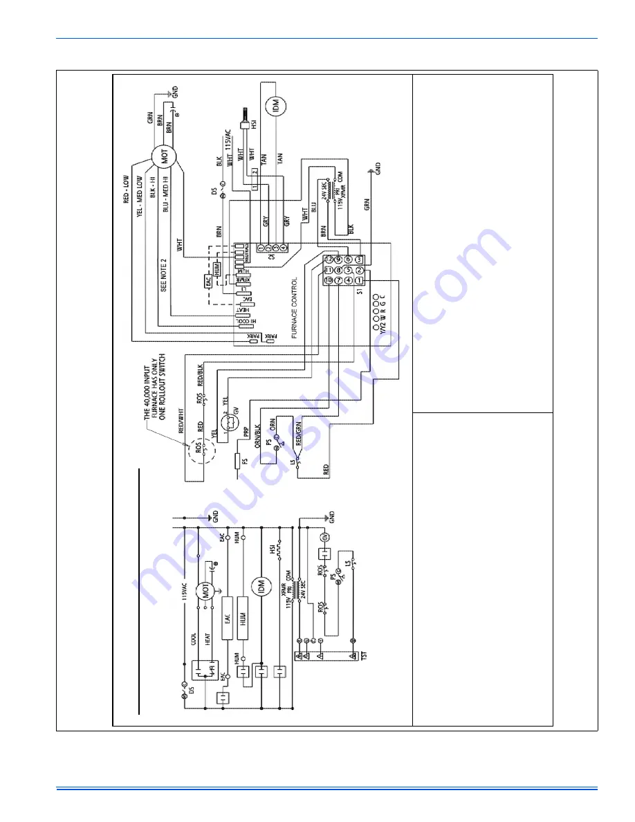
SECTION XI: WIRING DIAGRAM
FIGURE 28:
Wiring Diagram
LEGEND
DSDoorswitch
MOTCirculatin
g
motor
LSLimitswit
ch
ROSRolloutswitch
IDMInducermotor
HUMHumidif
ier
PSPressureswitch
F
SFlames
enso
r
CAPCapacitor
TSTWalltherm
ostat
GVGas
valve
XFMRTransformer
HSIHotsurfaceigniter
EACElectronic
aircleaner
1.Ifanyoftheoriginalwireassupplie
d
withthefurnacemustbe
replaced,itmust
ber
eplacedwithwiringma
terial
h
a
ving
a
t
emper
a
tur
e
r
a
ngof
a
tleas
t221
F
(105C).
2.Blower
motorspeedconnectionsshownaret
ypical,butmayvarybymodela
nd
application.
LEGENDE
DSCommutateurdeporte
MOTMoteursoufflerie
TSTThermosta
t
ROSCommutateurderoulement
IDMDinduct
moteur
FSCapteurdeflame
PSCommutateurdepression
EACFiltreélectrique
CAPCapaciteur
LSCommutateurdelimite
G
VSoupape
degaz
HUMHumidif
icateur
XFMRTransformeur
HSIIgnitionde
surfacechaud
1.Sil'undesfils
d'origine
fourniavecce
fourdoitêtreremplacé,ildoitêtreremplacéavec
lefilayantundegrédetempérat
ured'aumoins
221
F(105C).
2.Lesconnexion
sàgrand
evitessedumoteurd
u
ventilateurindiquéssonttypiqu
es,mais
peuventvarier
selonlemodèleetparapplication
.
Wiring
Diagram
80%SingleStageFurnace
348817-
UWD-D
-0810


