6
INSTALLATION MANUAL
Need help? Contact us at support@havenlock.com
INSTALLING YOUR IQ Lockdown
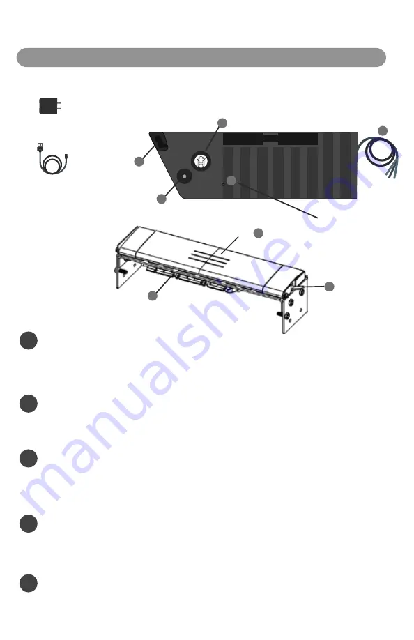
Charging Cable
USB Charging cable used to charge
your IQ Lockdown
Power Adapter
120v AC USB Adapter for use with
included charging cable
Included Items:
C
Control Panel
F
Hand Press
E
Locking Gate
Control Panel (inside of shell enclosure under shelf)
1
Charging
Push the Reset button (R) through the pinhole to wake the unit from shipping mode. Plug the included charging cable (USB end) into the
included power adapter. Open the Haven / IQ Lockdown Control Panel cover (C) and plug the charging cable into the Charging Port (D). The
status indicator LED will flash Yellow every 2.5 seconds when charging. Each lock comes with greater than a 30% charge. You may want to allow
IQ Lockdown to fully charge 6-8 hours before use.
2
Cycling the Lock
Cycling the lock a minimum of 10 times prior to installation ensures that the nylon straps inside the lock
are properly stretched and calibrated. During shipment parts can settle and this cycling allows the parts to “stretch” and maximize their effectiveness.
A “cycle” is simply locking and unlocking the lock via the hand press (F) and lock gate (E). Cycling the lock via the app a minimum of 5 times helps
ensure the servo motor is properly engaged and ready for use.
3
Include in Z-WAVE Network
Push the Pairing button (B) to start the inclusion process. See “Network Inclusion/Exculsion” in the Z-WAVE section for more details. After
inclusion, cycle the lock via the mobile app or customer site a minimum of 5 times to ensure proper opertion and servo cycling. Refer to
installation manuals for compatible panels for details on how to connect and control IQ Lockdown from these panels. The following are the
recommended compatible panels: DSC Power Series NEO, Power Series PRO, Qolsys IQPanel2, IQHub, and IQPanel4.
5
Connect Hardwire Accessories
Your lock may come with a wire harness (G) protruding from the control panel. This wiring harness is used for connecting an accessory to the
lock. Before you proceed to hardwiring any accessory please follow the instructions on the hardwire accessory installation page.
D
Charging Port
B
Pairing Button
R
Reset Button (use pin)
A
Status Indicator
Wire Harness
G
Mounting Hardware,
Bracket, & Plate Cover
Hardware is listed on the install
diagram along with included
assembly components, bolts, and
tools required
*NOTE*
In order to mount the lock to a standard 2’ commercial frame and door you need to check several things. First confirm the door is either an
in-swing or an outward swinging door. This will dictate the bracket that you use. Second confirm that the frame is a 2” and/or can accept the
bracket and configuration. Third, confirm that the door is either solid core or a metal door that is in good condition. Check pages 10 and 11 for
further installation steps and instructions.
Preparation for Hardwre Installation
4


