M9000-310 and M9000-320 Series Weather Shield Enclosures Installation Instructions
5
12. Install the two conduit fittings included with the kit
into the enclosure base and secure them in place
using the threaded hex nuts.
13. Insert the appliance cord into one of the conduit
fittings so that the cable wrapping is visible inside
the enclosure. Tighten the conduit fitting to a
torque of 10 to 15 lb·in (1.1 to 1.7 N·m) to secure
the appliance cord in place.
14. Install the electric actuator onto the damper shaft
extension and the enclosure anti-rotation bracket.
Note:
Refer to the documentation included with the
electric actuator for complete installation instructions.
15. Reinstall the cover and gasket assembly and
secure it in place using the four cover screws
included with the kit. Tighten the cover screws to a
torque of 5 to 8 lb·in (0.6 to 0.9 N·m) maximum.
16. If one of the conduit fittings remains unused, seal
the fitting using the cap plug included with the
enclosure kit.
Iron Flanged Valve Applications
Mount the weather shield enclosure onto the M9000-
53x Series Valve Linkage as follows:
1.
Loosen the four cover screws using a No. 1 Phillips
screwdriver and remove the cover and gasket
assembly from the enclosure base.
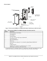
2.
Orient the anti-rotation bracket onto the enclosure
as illustrated in Figure 3.
Note:
The anti-rotation bracket must be oriented
properly in order for the anti-rotation tab to align with
the slot on the electric actuator.
3.
Secure the anti-rotation bracket to the threaded
brass inserts of the enclosure base using two
M3 x 8 mm Phillips screws and M4 washers
included with the kit. Tighten the Phillips screws to
a torque of 15 to 20 lb·in (1.7 to 2.3 N·m).
4.
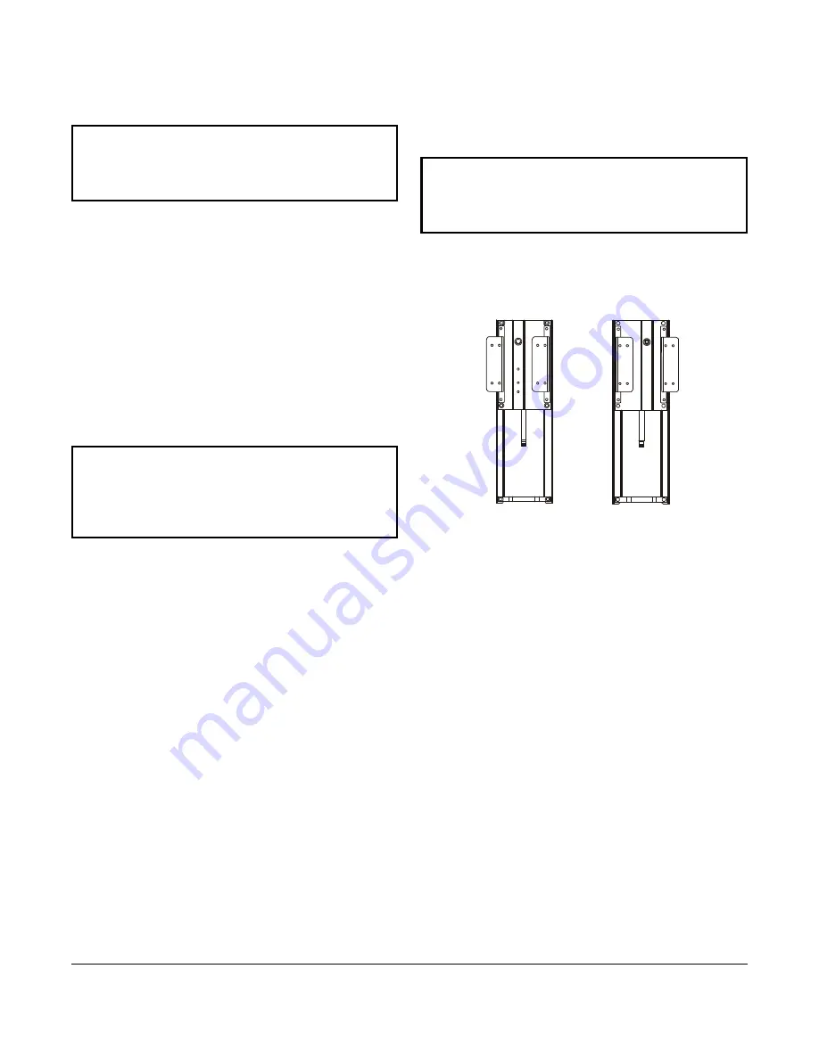
Orient the two mounting brackets onto the primary
side of the M9000-53x Series Valve Linkage (for
single-mount applications) as illustrated in
Figure 5.
5.
Secure the mounting brackets to the M9000-
53x Series Valve Linkage using four No. 12-24 x 1/
2 in. hex-head screws (included with the kit).
6.
Install the enclosure onto the input shaft of the
M9000-53x Series Valve Linkage. Orient the
enclosure so that the flanges of the mounting
brackets are flush with the surface of the enclosure
base.
7.
Secure the enclosure to the mounting brackets
using four No. 12-24 x 1/2 in. hex-head screws
included with the kit. Tighten the hex-head screws
to a torque of 20 to 25 lb·in (2.3 to 2.8 N·m).
Note:
Each hex-head screw should be inserted from
the inside of the enclosure so that the nitrile patch
seals the mounting hole in the base.
IMPORTANT:
The conduit fittings must be installed
properly to ensure a tight seal. Water or moisture
may damage or affect the operation of the electric
actuator within the enclosure.
IMPORTANT:
The cover and gasket assembly
must be installed properly to ensure a tight seal.
Water or moisture may damage or affect the
operation of the electric actuator within the
enclosure.
IMPORTANT:
Do not overtighten the Phillips
screws. Overtightening may cause the threaded
inserts located in the enclosure base to become
dislodged, resulting in damage to the enclosure.
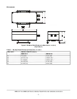
Secondary Side of
M9000-53x Series
Valve Linkage
Primary Side of
M9000-53x Series
Valve Linkage
F
IG
:m
n
tb
rk
t5
3
x
Figure 5: Proper Orientation of the
Mounting Brackets onto the M9000-
53x Series Valve Linkage


