


Network Communications—N2 Communications Bus
35
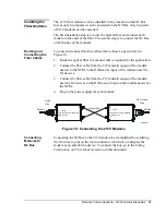
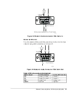
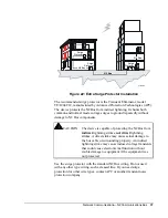
9-pin Connector
eol-in
Optional
Shield
Fold back
and tape.
Solder jumper wires between Pins 3-7 and Pins 8-9.
N2 -
REF
N2 +
Figure 19: Modem’s Cable Connector: EOL Set to In
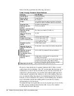
Modem Set EOL=Out
To set the modem with the end-of-line selection set to Out, wire the 9-pin
connector using solder connections as in Figure 20:
eol-out
N2 +
9-pin Connector
REF
Optional
Shield
Fold Back
and Tape
N2 -
Figure 20: Modem’s Cable Connector: EOL Set to Out
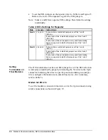
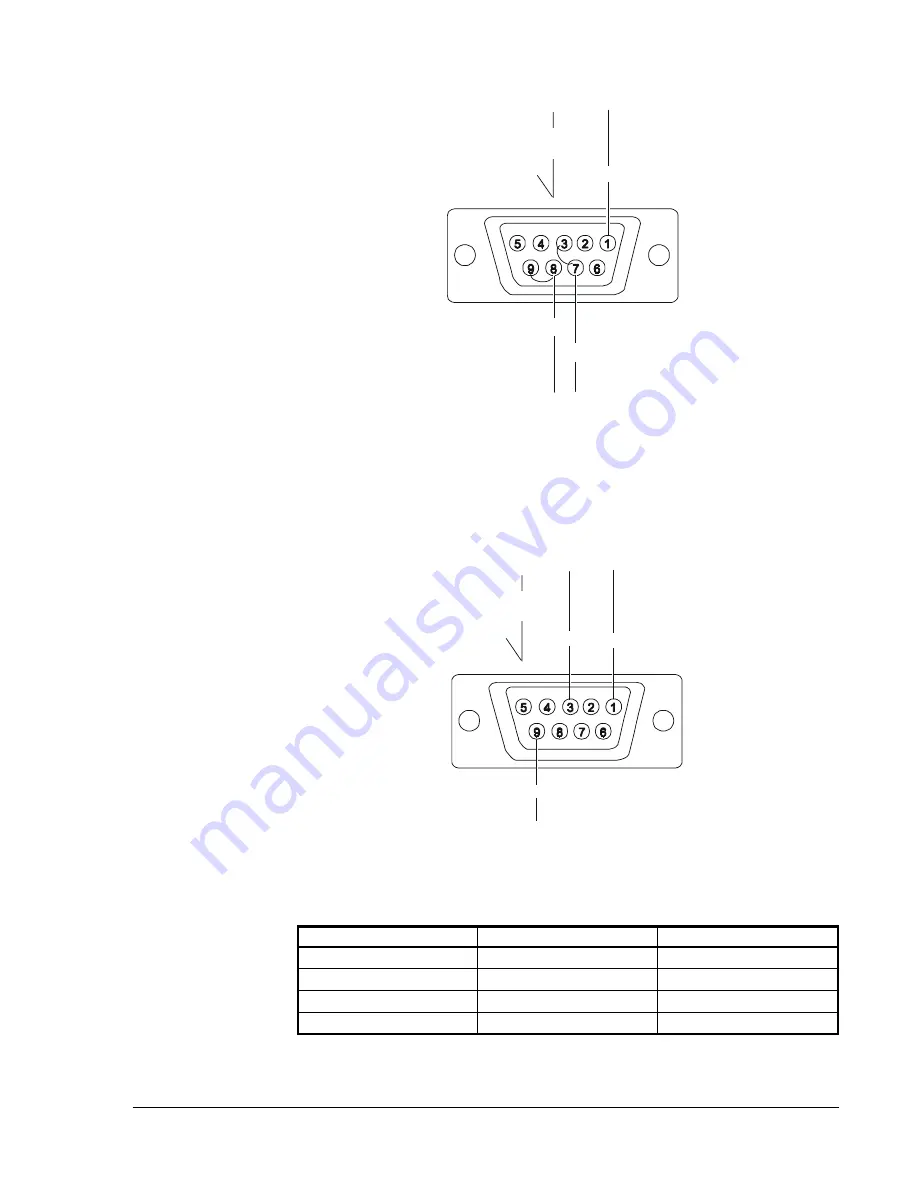
Table 5: EOL Connections Summarized
N2 Bus Signal
For EOL Selection
For Non-EOL Selection
N2 +
Terminal 7, Jumper 7 - 3
Terminal 3
N2 -
Terminal 8, Jumper 8 - 9
Terminal 9
REF
Terminal 1 or 5
Terminal 1 or 5
SHIELD
Tape Back
Tape Back


