Network Communications—N2 Communications Bus
39
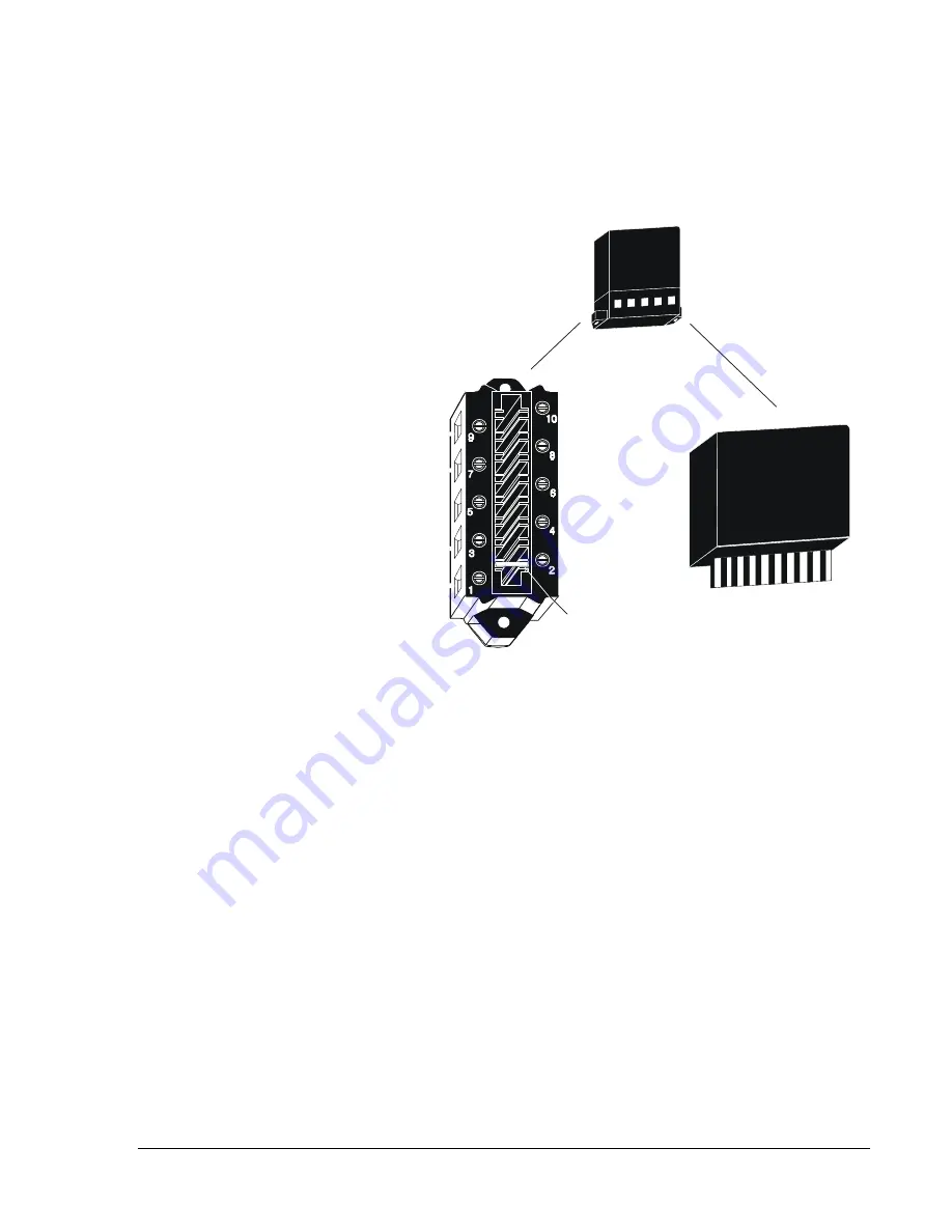
The surge protector consists of two sections: the terminal block and the
main assembly. These sections separate to make the unit easier to install
and replace. Refer to Figure 23.
Terminal Block
N2+
N2-
N2 REF
HRD GND
SFT GND
SFT GND
N2 REF
N2-
N2+
HRD GND
protectr
Keypin Between
Terminals 1 and 2
Main Assembly
Surge Protector
Unprotected Side
Protected Side
Figure 23: Sections of Surge Protector
How the Surge Protector is wired depends on which device requires
protection. Refer to Figures 24 through 30 for the wiring diagrams for all
the various N2 devices. Also, follow these general steps:
1. Mount the device per local codes and install in an enclosure
(if necessary) as close as possible to the N2 device. Any electrical box
with a cover is acceptable. Bond the enclosure to the N2 device by
connecting the two with conduit that carries the N2 cable.
Note: For extra protection, you may as an option, install a second
protector at the point where the N2 Bus enters the building.
Also, install that unit in a separate enclosure (if necessary).
2. Connect the N2 segment from the outside to the unprotected side of
the device. If possible, run the segment inside metallic conduit, since
the conduit acts like a shield for lightning.
3. Connect the N2 segment that will go to the N2 device to the protected
side of the device. Keep this segment away from the unprotected
segment.


