24
Network Communications—N2 Communications Bus
The N2 Bus is wired to the communication terminal board of the NCU or
NEU using the terminal block labeled TB1. Wire the N2 Bus as shown in
Figure 10 (TBC801) or Figure 11 (TBC821). Be sure to follow these rules:
•
Always make sure the input wires you connect to the N2 terminals are
twisted together and the output wires from the N2 terminals are twisted
together. This is shown in Figures 10 and 11. Also, keep these wires
twisted up to within an inch or two of the actual screw terminals.
•
To maintain consistency throughout the system, it is best to use the
same color wires for the N2 Bus (e.g., always use the orange/white
wire for N2+ and the white/orange wire for N2-). This should ensure a
working N2 Bus the first time it is wired, and make troubleshooting
easier should a problem occur.
•
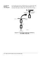
If the N2 wire has three conductors, terminate the third wire (and any
spare conductors) to REF, not to SFT GRD. Use the SFT GRD for a
shield only.
•
Shielded cable is generally not required, except in very high noise
environments, such as near gas ignition systems and radar or magnetic
resonance imaging equipment. If you must use shielded wire:
-
At each N2 device that does not have its own soft ground terminal
(e.g., ASCs), wire the shield to a 560 pF (1 Kv ceramic) capacitor
that is wired to earth ground. (If a 560 pF capacitor is not readily
available, one in the range of 560 to 1000 pF can be used.) At the
NCU and NEU, a capacitor is not needed, since the soft ground
termination at the TBC provides the required capacitance.
-
At only one NCU or NEU on the N2 Bus, wire the shield to earth
ground at the TBC.
Wiring--
NCU/NEU to
N2 Bus


