FCU Controller Installation
Guide
25
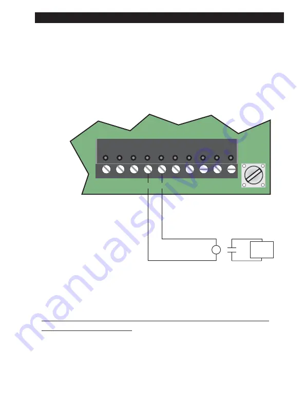
Wiring for the Cooling Stage 2 is shown in Figure 18. To wire DO3 for
Cooling Stage 2:
1
. Connect the
HOT
terminal to one side of the pilot relay’s coil.
2
. Connect the
DO3
terminal to the other side of the pilot relay’s coil.
3
. Wire the pilot relay’s output to the appropriate specifications for the
device.
J3
24 V
AC HOT
COOLING ST
AGE 2
COMPRESSOR
OR
VALVE
DO5 DO4 HOT DO3 DO2 HOT
AGND
AO1
DO1
HOT
Figure 18. DO3 - Cooling Stage 2 Wiring.
DIGITAL OUTPUTS DO4 AND DO5 - HEATING INC/DEC
OR STAGE 1/2 WIRING
NOTE:
The rating for this output is 0.5 amps at 24VAC.
Digital outputs 4 and 5 must be wired to the Heating Increment/Heating Stage
1 and the Heating Decrement/Heating Stage 2.


