Operating manual- SAB 355 (including ATEX)
004059 en 2019.11
43/63
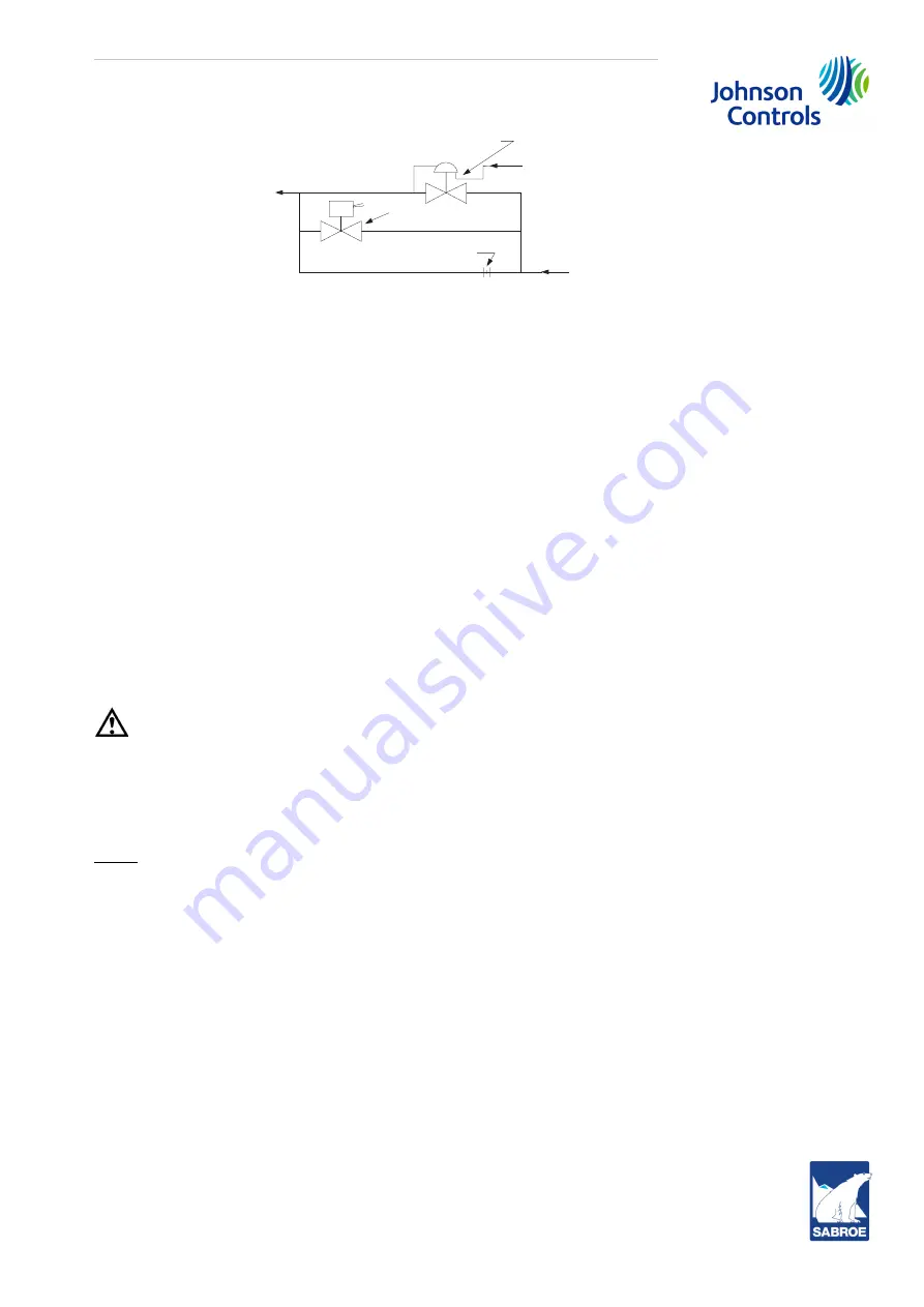
Fig. 23: High-stage SB-2 oil supply line diagram (SAB 355 H only)
6.19
Low ambient temperature operation
It is recommended that oil separators are insulated as a minimum requirement to preserve the
heat generated by the oil heaters. It is important that the coalescer end of the separator is insu-
lated to prevent refrigerant condensation.
On systems located outdoors, or in unheated buildings, where the ambient temperature may drop
below 0° C, insulation and heat tracing of the compressor lubricating oil systems, including oil
lines, oil filters, oil pumps and oil coolers, is mandatory. Freeze-up protection must also be pro-
vided for all water-cooled equipment.
SABROE heat pumps always have insulation and heat tracing.
6.20
Heating element
To keep the compressor lubricating oil warm during a period of standstill, a heating element is
built into the oil reservoir. Before start-up, the heating element must be switched on for 6-8 hours
to ensure that only a minimum of refrigerant remains in the oil. If there is too much refrigerant in
the oil, the oil loses its lubricating properties.
Warning!
The heating element must not be switched on if the oil level in the reservoir is below minimum in
the sight glass. Normally, it must be turned off when the compressor is in operation.
Remember to turn off the heating element before draining the oil through the compressor service
valve and before opening into the oil reservoir for inspection.
ATEX:
On ATEX-executions, the heating element(s) are ATEX-approved. Heating elements from Johnson
Controls Denmark have a thermostat with manual reset. If the thermostat drops out, only compe-
tent personnel should reactivate it.
6.21
Start-up
Preparations before start-up
1.
Turn on the power voltage and the control voltage. Check the emergency stop button.
2.
Check the oil level in the oil separator, see subsection
8.4 Oil .
3.
Check that all valves are positioned in accordance with
Table 6: Valve positions during op-
including the secondary side of the oil cooler.
4.
Reset all alarms according to the control system instructions.
5.
Check on the control display that the compressor capacity control system is in minimum
slide pos. 0-4%.
Pressure-regulating valve(A4ALE)
From compressor
discharge or oil
manifold
Solenoid valve
Restriction orifice (pipe)
From oil manifold
To SB-2
compressor
port


