Operating manual- SAB 355 (including ATEX)
34/63
004059 en 2019.11
Fig. 14: Shaft rotation
The compressor rotation is clockwise when facing the compressor drive shaft. See
Fig. 14. The compressor must never be operated in reverse rotation as this will cause
bearing damage.
6.6
Compressor lubrication system
The lubrication system on a screw compressor unit performs several functions:
•
It provides lubrication to bearings and seal.
•
It provides a cushion between the rotors to minimise noise and vibrations.
•
It helps keep the compressor cool and prevents overheating.
•
It provides an oil supply to hydraulically actuate the slide valve and slide stop.
•
It provides oil pressure to the balance pistons to increase bearing life.
•
It provides an oil seal between the rotors to prevent rotor contact or gas bypassing.
The compressor unit may be equipped with either a “no pump” or a “demand pump” lubrication
system. Additionally, either system may contain:
•
Dual oil filters and liquid injection.
•
Water-cooled or thermosyphon oil cooler for compressor oil cooling.
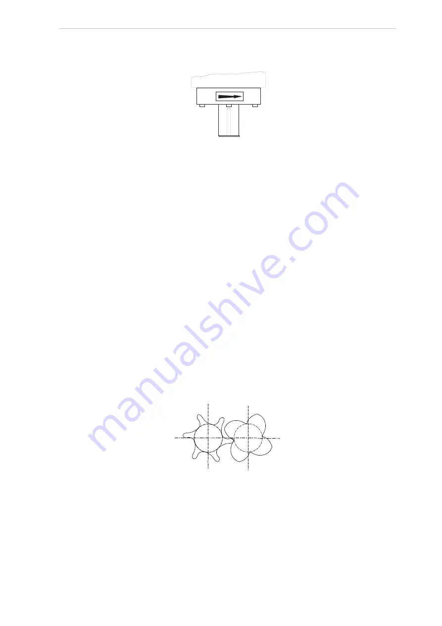
The rotors are constructed with an asymmetrical profile. The male rotor has four lobes, and the
female rotor has six, see Fig. 15.
Fig. 15: Female/male rotor
A shaft seal is mounted at the shaft end (driving shaft) of the male rotor. The shaft seal ensures
complete tightness between the compressor housing and the compressor shaft, thus preventing
atmospheric air from entering the compressor.
6.7
No pump oil system
The screw compressor unit is designed to be self-lubricating. Oil supplied to the compressor from
the oil separator is at system head pressure. In the compressor, oil from all lubricating points is
returned to a point in the compressor body where the pressure is lower than the compressor
COMPRESSOR
Female
Male


