S9210-BxC / S9220-BxC
1
English
READ THIS INSTRUCTION SHEET AND THE SAFETY WARNINGS
CAREFULLY BEFORE INSTALLING AND SAVE IT FOR FUTURE USE
General Features
The On/Off Fire Electric Spring Return Actuators are direct-mount, spring, bidirectional
actuators and do not require a damper linkage. The actuators are intended to be
installed on a fire damper. The actuators operate on AC 24 V power at 50/60 Hz,
DC 24 V power or AC 230 V power at 50/60 Hz.
When the control signal is applied the actuator drives the damper to the operational
position, while evenly tensioning the integrated spring. After a power failure the stored
energy in the spring immediately brings the damper to the safety position.
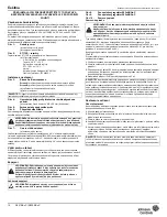
Figure 1:
Dimensions in mm
(a).
Mounting Hole (6 Locations)
(b).
Shaft coupler
Figure 2:
ST1.72E Dimensions
The ST1.72E temperature sensor is directly connected to the actuator.
(a).
Connection cable:
0.6 m UL758 type AWM Halogen-free
Temperature: -20 °C...+55 °C
Switch point of temperature sensor:
ST1.72E = ca. 72 °C
Standard:
Halogen-gas-emission: IEC60754-1
Fire resistant: IEC60332-1
Installation and adjustment
Figure 3:
Side A and B of actuator
Side A:
CCW Spring Return Direction
Side B:
CW Spring Return Direction
(a).
Auxiliary switch adjuster
(b).
Manual Override
Figure 4:
Fitting the Anti-rotation Bracket on the Damper Frame
or Duct
(a).
M3 x 9.5 mm. Self - Drilling Sheet Metal Screw (Two Locations)
Figure 5:
Changing the position of the coupler
Figure 6:
Allowed shaft lenght
Attach the actuator to the damper spindle by means of the adapter and secure the
locking device with the screws provided.
Figure 7:
Angle of rotation limiting
(a).
Stroke limiting
The actuator is factory set for 90° rotation. Attaching a stroke limiting stop (optional
M9220-603 Adjustable Stop Kit) in the farthest mounting position will reduces the
rotation range of the actuator by 5°. Each progressive mounting position reduces the
rotation range an additional 5° to a maximum of 30° in either end stop position.
Selecting the direction of rotation
For CCW spring return direction, mount the actuator to the damper shaft so that Side A
of the actuator is away from the damper as illustrated in Figure 2. To change the spring
return direction to CW, mount the actuator to the damper shaft so that Side B of the
actuator is away from the damper.
Wiring
Wiring Diagrams
Figure 8:
S92x0-BGx-C ON/OFF Control
Figure 9:
S92x0-BDx-C ON/OFF Control
Figure 10: Auxiliary Switch
Auxiliary Switches
These models include two integral auxiliary switches, one fixed (S1) and one adjustable
(S2), accessible on either face of the actuator
(as illustrated in Figure 2).
The nominal
factory setting for S1 Auxiliary Switch is 11° closing, and the nominal factory setting for
S2 Auxiliary Switch is 81° opening (relative to a 0 to 90° rotation range).
The switch point of S2 Auxiliary Switch is independently and continuously adjustable
from 25 to 95°.
Use the method in the following example for the most accurate positioning of S2
Auxiliary Switch.
1.
Move the actuator to the full spring return position.
2.
Rotate the switch adjuster until it points to the desired switch point.
3.
Connect S2 Auxiliary Switch to a power source or an ohmmeter, and apply power to
the actuator. The actuator moves to the fully open position and holds while power is
applied.
4.
Observe the switch point. If required, repeat Steps 2 and 3.
Setup and Adjustment
Manual Override
Use only the supplied manual override crank to reposition the actuator hub when using
the manual override feature.
1.
De-energize the actuator.
2.
Insert the hex end of the manual override crank into the manual override adjustment
point on the face of the actuator.
3.
Rotate the manual override crank in the direction indicated by the arrow on the label.
4.
Rotate the manual override crank a half turn in the opposite direction to lock the
actuator hub in place.
5.
To unlock the actuator hub, rotate the manual override crank in the direction indicated
by the arrow on the label. The actuator hub automatically unlocks when power is
applied to the actuator, and returns the actuator to normal drive and spring return
operation.
IMPORTANT:
When calculating the torque required to operate dampers, it is essential
to take info account all the data supplied by the damper manufacturer.
WARNING: Do not install or use this Proportional Electric Spring Return
Actuator in or near environments where corrosive substances or vapors
could be present. Exposure of the electric actuator to corrosive
environments may damage the internal components of the device, and
will void the warranty.
WARNING: The electrical connections for the actuators must be
executed in accordance with the relevant legal requirements.
In order to avoid any personal injury or damage to the equipment or
other property, always isolate the power supply before commencing any
work on the electrical wiring. In order to avoid danger to property, it is
important for the equipment to be used solely for which it is intended.
WARNING: The integrated circuits in the actuator are sensitive to static
electricity. Take suitable precautions.
WARNING: Disconnect each of multiple power supplies before making
electrical connections.
More than one disconnect may be required to completely de-energize
equipment. Contact with components carrying hazardous voltage can
cause electric shock and may result in severe personal injury or death.
IMPORTANT:
Use the Proportional Electric Spring Return Actuator only to control
equipment under normal operating conditions. Where failure or malfunction of the
electric actuator could lead to personal injury or property damage to the controlled
equipment or other property, additional precautions must be designed into the control
system. Incorporate and maintain other devices such as supervisory or alarm system
or safety or limit controls intended to warn of, or protect against, failure or malfunction
on the electric actuator.
IMPORTANT:
Applying excessive torque to the manual override or running the
manual override with a power tool may damage the internal components of the
actuator and cause premature failure. At the end of travel, the rotational resistance
increases; do not force the actuator hub past this point.
This document is subject to change without notice


