Engineering manual - SAB 193-233-283 S A-frame (including ATEX)
008831 en 2020.10
47/168
unload side of the cylinder. Simultaneously, oil contained in the load side of the cylinder flows out
of compressor port SC2 through valve ports B and T to compressor suction side.
Note:
To control the rate of loading and unloading, change cycle time, proportional band and
dead band set points with the control system. If additional control is needed, throttle SC2 or BP.
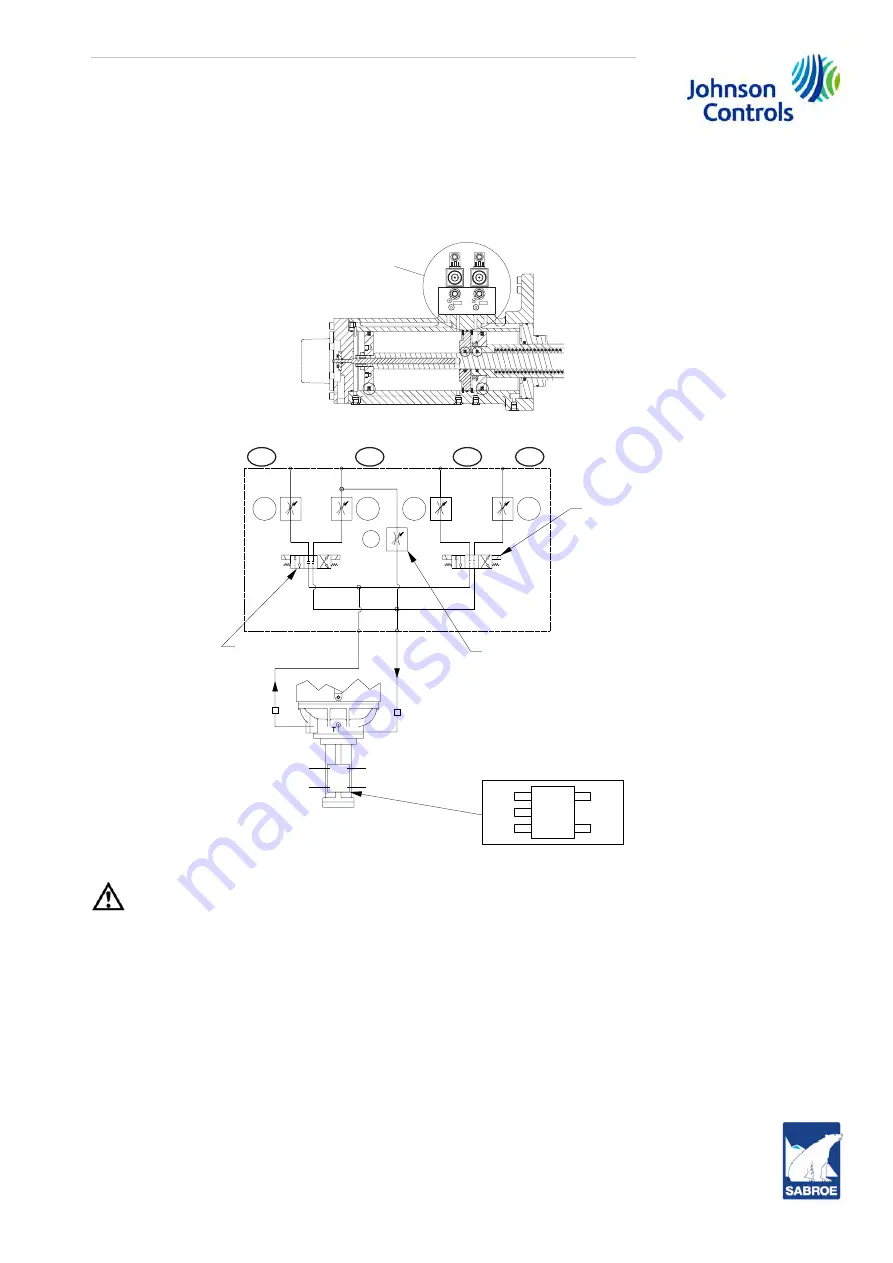
Fig. 25: Volumizer volume ratio and capacity control
Fig. 26: Compressor hydraulic system
Caution!
Never
open valve BP and valve SC2 at the same time during compressor operation.
See Fig. 26 for port references.
•
Open valve at SC3
•
SC4 not used
Compressor V
i
increase.
The volume ratio V
i
is increased when the MSS solenoid valve, YY3, is
energised, and oil flows from the oil manifold through the valve ports, P and A, to the compressor
port, SC3, enters the increase side of the cylinder and overcomes the decrease spring tension.
The inboard side of the slide stop piston is at suction pressure.
Compressor V
i
decrease.
The volume ratio V
i
is decreased when the MSS solenoid valve, YY4,
is energised, which permits oil to vent from port A to T with assistance from the unloader spring
via port SC3.
To control the rate of the V
i
change, throttle the needle valve at the SC3 port.
SC1
SC3
See hydraulic
schematic for
functional
view of valve
operation
Screw in
flow-regulating
needle valve
Hydraulic schematic
sizes: 100-480, 546
SC3
SC1
SC4
BP
SC2
YY4 (Decrease Vi)
YY2 (Load)
(Increase Vi) YY3
(Unload) YY1
Direction
control valve
SV-2
YY2
YY1
YY3
YY4
SV-3
SC4
SC3
SC2
SC1
T
T
P
P
A
B
BP
1
2
1
2
2
1
T
P
A
B
1
2
1
2
SC3
SC4
SC2
SC1
182
181
183
184
Direction
control
valve
Compressor top view
P
Summary of Contents for Sabroe SAB 193 L
Page 1: ...SAB 193 233 283 S A frame including ATEX Screw compressor units Engineering manual en ...
Page 2: ......
Page 169: ......


